
9.6.1 I2C Client Interface Timing Diagram
The I2C Client timing diagram for the ATWILC3000A is shown in the following figure.
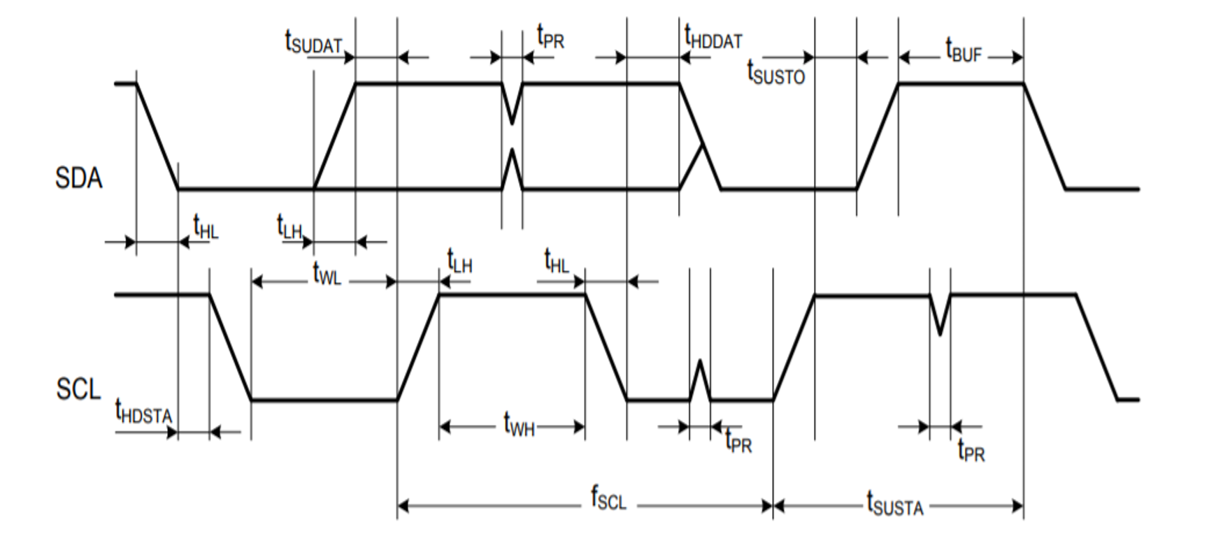
The following table provides the I2C Client timing parameters for the ATWILC3000A.
| Parameter | Symbol | Min. | Max. | Units | Remarks |
|---|---|---|---|---|---|
| SCL Clock Frequency | fSCL | 0 | 400 | kHz | — |
| SCL Low Pulse Width | tWL | 1.3 | — | µs | — |
| SCL High Pulse Width | tWH | 0.6 | — | — | |
| SCL, SDA Fall Time | tHL | — | 300 | ns | — |
| SCL, SDA Rise Time | tLH | — | 300 | This is dictated by external components | |
| Start Setup Time | tSUSTA | 0.6 | — | µs | — |
| Start Hold Time | tHDSTA | 0.6 | — | — | |
| SDA Setup Time | tSUDAT | 100 | — | ns | — |
| SDA Hold Time | tHDDAT | 0 | — | ns | Client and Host default |
| 40 | — | µs | Host programming option | ||
| Stop Setup Time | tSUSTO | 0.6 | — | µs | — |
| Bus Free Time between Stop and Start | tBUF | 1.3 | — | — | |
| Glitch Pulse Reject | tPR | 0 | 50 | ns | — |