
2.6 Using a USART/UART
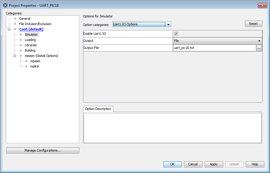
For devices that have a USART or UART peripheral, USART/UART simulation may be enabled using File>Project Properties, “Simulator” category, “UART1 IO Options” option category. For more on this category, see Simulator Options Selection.
For an example of simulating USART/UART operation, see below.
PIC18F MCU USART Example – Setup
Follow the steps below to set up the example.
- Get Example Code: Example code
for demonstrating USART operation in the simulator is based on code found on the
Microchip website under “PICDEM™ 2 example code” as “USART demo for the 18CXXX”
(
usart.asm). The updated code (usart2.asm) is listed in the code at the end of the example. - Create a Project: In MPLAB X IDE, use the Project Wizard to create a project.
- Select “Microchip Embedded”, “Standalone Project”.
- Select PIC18F452 as the device.
- Select the Simulator as the “hardware” tool.
- Select “mpasm” as the active toolchain.
- Place the project in its own folder and name the project “usart”.
- Add Source File: Add the file
usart2.asmto the project:- Right click on “Source File” in the project tree and select
New>Other. In the “New File” window, click the “Assembler”
category, select “AssemblyFile.asm” and click Next. Name the file
usart2.asmand click Finish. The new file will appear in the project tree and open in an Editor window. Paste in the example code and save the file. - Right click on “Source File” in the project tree and “Add Existing Item” if you have already created the file outside of MPLAB X IDE.
- Right click on “Source File” in the project tree and select
New>Other. In the “New File” window, click the “Assembler”
category, select “AssemblyFile.asm” and click Next. Name the file
- Check Assembler Location: Make sure the paths to the language tool executables are correct (see the Tools>Options, Embedded button, Build Tools tab.)
- Build the Project: Right click on the project name in the project tree and select “Build”. Build results are displayed in the Output window. Fix any reported errors.
PIC18F MCU USART Example – Register Injection
To use register injection:
- Enable the UART:
- Right click on your project and select “Properties”.
- Click on the “Simulator” category and select the option category “Uart1 IO Options”.
- Check “Enable Uart1 IO”.
- For “Output”, select “Window”.
- Click Apply.
- Select Window>Simulator>Stimulus.
- Click the “Register Injection” tab.
- Under “Reg/Var”, select the UART receive register (e.g., RCREG or RXBUF), depending on your device.
- Under “Trigger, select “Message”.
- Select File>New File, “Other” category, “Empty File” file type and
click Next. Name the file “input.txt” and click Finish. Enter the following into
the file in the editor and then select
File>Save.
wait 4 ms “Microchip” - Under “Data Filename”, enter the name of the file in the previous step.
- Under “Format”, choose “Pkt”.
- Debug Run the program. The injected output will be displayed in the Output window, “UART 1 Output” tab.
Updated PICDEM 2 Example Code
;
; Software License Agreement
;
; The software supplied herewith by Microchip Technology Incorporated
; (the “Company”) for its PIC(R) Microcontroller is intended and
; supplied to you, the Company’s customer, for use solely and
; exclusively on Microchip PIC Microcontroller products. The
; software is owned by the Company and/or its supplier, and is
; protected under applicable copyright laws. All rights are reserved.
; Any use in violation of the foregoing restrictions may subject the
; user to criminal sanctions under applicable laws, as well as to
; civil liability for the breach of the terms and conditions of this
; license.
;
; THIS SOFTWARE IS PROVIDED IN AN “AS IS” CONDITION. NO WARRANTIES,
; WHETHER EXPRESS, IMPLIED OR STATUTORY, INCLUDING, BUT NOT LIMITED
; TO, IMPLIED WARRANTIES OF MERCHANTABILITY AND FITNESS FOR A
; PARTICULAR PURPOSE APPLY TO THIS SOFTWARE. THE COMPANY SHALL NOT,
; IN ANY CIRCUMSTANCES, BE LIABLE FOR SPECIAL, INCIDENTAL OR
; CONSEQUENTIAL DAMAGES, FOR ANY REASON WHATSOEVER.
;
;***********************************************************
;   PIC18F452 EXAMPLE CODE FOR PICDEM 2
;
;   TITLE: USART Demonstration
;   FILENAME: usart.asm
;   REVISION HISTORY:  A 05/13/00 jb   format change
;                      B 02/28/05 em   update for example
;                      C 10/16/14 em   disable WDT
;   HARDWARE: PICDEM 2 board
;   FREQUENCY: 4MHz
;
;************************************************************
; This program demonstrates basic functionality of the USART.
;
; Port B is connected to 8 LEDs.
; When the PIC18F452 receives a word of data from
; the USART, the value is displayed on the LEDs and
; is retransmitted to the host computer.
;
; Set terminal program to 9600 baud, 1 stop bit, no parity

   list p=18f452       ; set processor type
   list n=0            ; suppress page breaks in list file
   include <p18f452.inc>

; Turn off Watchdog Timer
   config WDT=OFF

;************************************************************
; Reset and Interrupt Vectors

   org    00000h       ; Reset Vector
   goto   Start

   org    00008h       ; Interrupt vector
   goto   IntVector

;************************************************************
; Program begins here

   org    00020h       ; Beginning of program EPROM
Start
   clrf   LATB         ; Clear PORTB output latches
   clrf   TRISB        ; Config PORTB as all outputs
   bcf    TRISC,6      ; Make RC6 an output

   movlw  19h          ; 9600 baud @4MHz
   movwf  SPBRG

   bsf    TXSTA,TXEN   ; Enable transmit
   bsf    TXSTA,BRGH   ; Select high baud rate

   bsf    RCSTA,SPEN   ; Enable Serial Port
   bsf    RCSTA,CREN   ; Enable continuous reception

   bcf    PIR1,RCIF    ; Clear RCIF Interrupt Flag
   bsf    PIE1,RCIE    ; Set RCIE Interrupt Enable
   bsf    INTCON,PEIE  ; Enable peripheral interrupts
   bsf    INTCON,GIE   ; Enable global interrupts

;************************************************************
; Main loop

Main
   goto   Main         ; loop to self doing nothing

;************************************************************
; Interrupt Service Routine

IntVector
; save context (WREG and STATUS registers) if needed.

   btfss  PIR1,RCIF  ; Did USART cause interrupt?
   goto   OtherInt   ; No, some other interrupt

   movlw  06h        ; Mask out unwanted bits
   andwf  RCSTA,W    ; Check for errors
   btfss  STATUS,Z   ; Was either error status bit set?
   goto   RcvError   ; Found error, flag it

   movf   RCREG,W    ; Get input data
   movwf  LATB       ; Display on LEDs
   movwf  TXREG      ; Echo character back
   goto   ISREnd     ; go to end of ISR, restore context, return

RcvError
   bcf    RCSTA,CREN ; Clear receiver status
   bsf    RCSTA,CREN
   movlw  0FFh       ; Light all LEDs
   movwf  PORTB
   goto   ISREnd     ; go to end of ISR, restore context, return

OtherInt
   goto   $          ; Find cause of interrupt and service it
                     ; before returning from interrupt. If not,
                     ; the same interrupt will re-occur
                     ; as soon as execution returns to
                     ; the interrupted program.

ISREnd
; Restore context if needed.
   retfie

   end