2.9.2 Step 2: Creating Simulation Topology
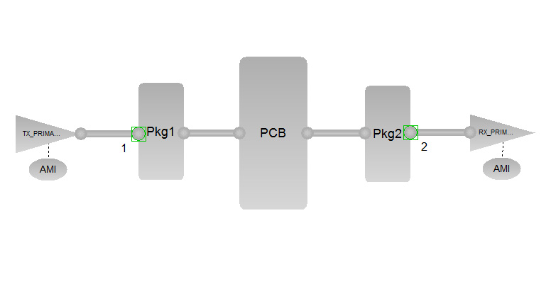
(Ask a Question)The typical topology, as shown in the following figure, shows the blocks involved in the serial link analysis. These blocks are taken from the Sigrity tool. All simulations related to SerDes are done on Sigritys SystemSI tool in this document. Topology is same in any tool. This can be done in any tool that supports the serial link analysis.
The typical topology for SLA simulation is listed as follows:
- AMI: AMI models of TX and RX
- TX_PRIMARY: IBIS model of TX I/O
Pkg1 and Pkg2: Package model of TX and RX I/O
PCB: S-parameter model of SmartFusion2 Development Kit SerDes Traces
RX_PRIMARY: S-parameter model of either the connector or the IBIS model of the receiver IC device
Once all the model files are imported into the topology, the default configuration in the AMI model must be left to calculate the appropriate coefficients by the tool and then to run the simulations.