1.3 CCP Capture Mode
This example shows how to use the CCP module in capture mode to measure pulse width of an input signal.
Description
In this application, a pulse signal is generated using the compare mode of CCP peripheral and is fed to the capture input. CCP peripheral captures the time at every edge and displays the pulse width on the serial terminal.
Downloading and building the application
To clone or download this application from Github, go to the main page of this repository and then click Clone button to clone this repository or download as zip file.
Path of the application within the repository is apps/ccp/ccp_capture_mode.
To build the application, refer to the following table and open the project using its IDE.
| Project Name | Description |
|---|---|
| pic32ak_gc_curiosity.X | MPLABX project for Curiosity Platform Development Board and PIC32AK1216GC41064 General Purpose Dual In-Line Module (DIM) |
Setting up the hardware
The following table shows the target hardware for the application projects.
| Project Name | Description |
|---|---|
| pic32ak_gc_curiosity.X | Curiosity Platform Development Board and PIC32AK1216GC41064 General Purpose Dual In-Line Module (DIM) |
Setting up Curiosity Development Board
- Connect the pin 3 (ICM1 - RB3) of XPRO1 Header to pin 4 (OCM2 - RB9) of XPRO1 Header
- Insert the GP DIM on to DIM slot of Curiosity Board
- Connect the PKoB (J24) on the board to the computer using a USB type-C cable
Running the Application
- Open the Terminal application (Ex.:Tera term) on the computer
- Connect to the “PICkit 4 On Board
Virtual COM Port” and configure the serial settings as follows:
- Baud : 115200
- Data : 8 Bits
- Parity : None
- Stop : 1 Bit
- Flow Control : None
- Build and Program the application project using its IDE
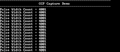
- Console displays the captured
pulse width as shown below: