
1.13 PWM Generators Synchronous Output
This example application demonstrates how to Synchronize multiple PWM Generators buffer update to get synchronous output.
Description
This example demonstrates the configuration of multiple PWM generators to produce synchronous outputs. The PWM Generator 1 acts as the host(using MSTEN control bit) and controls the register updates of other PWM generators (clients). The duty cycles of all PWM generators are dynamically updated within the interrupt handler.
Downloading and Building the Application
To clone or download this application from Github, go to the main page of this repository and then click Clone button to clone this repository or download as zip file. This content can also be downloaded using content manager by following these instructions.
Path of the application within the repository is apps/pwm/pwm_synchronous_output.
To build the application, refer to the following table and open the project using its IDE.
| Project Name | Description |
|---|---|
| pic32ak_gc_curiosity.X | MPLABX project for Curiosity Platform Development Board |
Setting Up the Hardware
The following table shows the target hardware for the application projects.
| Project Name | Description |
|---|---|
| pic32ak_gc_curiosity.X | Curiosity Platform Development Board |
Setting Up Curiosity Platform Development Board
- Connect a PIC32AK1216GC41064 General Purpose Dual In-Line Module (DIM) to the J1 header
- Connect Pin P28, P30, P32 and
P34 to oscilloscope or Logic Analyzer
- P28 - PWM1H
- P30 - PWM2H
- P32 - PWM3H
- P34 - PWM4H
- Connect the Debug USB port on the board to the computer using a micro USB cable
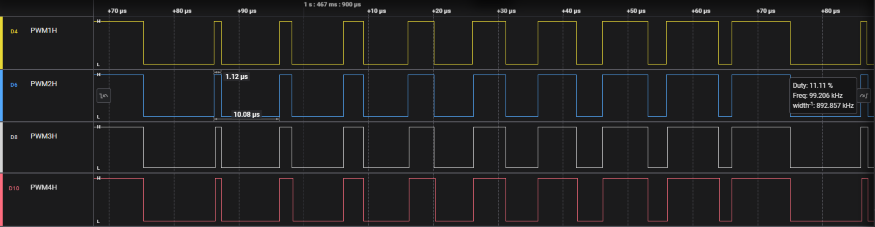
Running the Application
- Build and Program the application project using its IDE
- Observe the PWM1H, PWM2H, PWM3H,
PWM4H output in the oscilloscope or logic Analyzer
| Board | Output Pin |
|---|---|
| Curiosity Platform Development Board | P28, P30,P32, P34 |