1.1 ADC Interrupt
This example application shows how to sample an analog input using the ADC peripheral and displays the converted samples on a serial terminal.
Description
In this application, an analog input is converted by a manual software trigger. Result is read in the conversion complete interrupt handler. Converted digital value is displayed on the serial terminal.
Downloading and Building the Application
To clone or download this application from Github, go to the main page of this repository and then click Clone button to clone this repository or download as zip file.
Path of the application within the repository is apps/adc/adc_interrupt/.
To build the application, refer to the following table and open the project using its IDE.
| Project Name | Description |
|---|---|
| pic32ak_gc_curiosity_platform.X | MPLABX project for Curiosity Platform Development Board and PIC32AK1216GC41064 General Purpose Dual In-Line Module (DIM) |
Setting Up the Hardware
| Project Name | Description |
|---|---|
| pic32ak_gc_curiosity_platform.X | Curiosity Platform Development Board and PIC32AK1216GC41064 General Purpose Dual In-Line Module (DIM) |
Setting Up Curiosity Platform Board and DIM
- Insert the GP DIM on to DIM slot of Curiosity Board
- Connect the PKoB (J21) on the board to the computer using a USB type-C cable
Running the Application
- Open the Terminal application (Ex.: Tera term) on the computer
- Connect to the “PICkit 4 On Board
Virtual COM Port” and configure the serial settings as follows:
- Baud : 115200
- Data : 8 Bits
- Parity : None
- Stop : 1 Bit
- Flow Control : None
- Build and Program the application project using its IDE
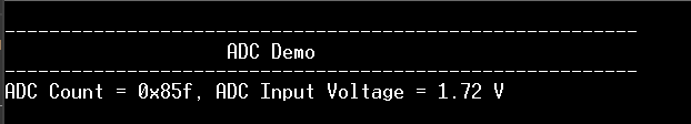
- Console displays the ADC count
and the ADC input voltage