1.6 CLC Manchester Encoder
This example application shows how to use the CLC peripheral library and generate a Manchester-encoded output.
Description
This demonstrates a way to generate a Manchester-encoded output using a SPI port and the CLC. The SPI port is sending out a predefined buffer of data in a circular fashion. Data is sent out LSB first, with CLC1OUT being the Manchester-encoded output. Pins are configured such that a logic analyzer can be attached to see the input (SDO1 and REFO1) and the CLC1 output (CLC1OUT) simultaneously.
Downloading and building the application
To clone or download this application from Github, go to the main page of this repository and then click Clone button to clone this repository or download as zip file.
Path of the application within the repository is apps/clc/manchester_encoder.
To build the application, refer to the following table and open the project using its IDE.
| Project Name | Description |
|---|---|
| pic32ak_gc_curiosity.X | MPLABX project for Curiosity Platform Development Board and PIC32AK1216GC41064 General Purpose Dual In-Line Module (DIM) |
Setting up the hardware
The following table shows the target hardware for the application projects.
| Project Name | Description |
|---|---|
| pic32ak_gc_curiosity.X | Curiosity Platform Development Board and PIC32AK1216GC41064 General Purpose Dual In-Line Module (DIM) |
Setting up Curiosity Development Board
- Pin 3 (RB3) of XPRO1 header has REFO1 output, which is internally connected to CLC1
- Pin 16 (RC6) of XPRO1 header has SDO1 output, which is internally connected to CLC1
- Pin 5 (RC8) of XPRO1 header has CLC1 output (CLC1OUT)
- Insert the GP DIM on to DIM slot of Curiosity Board
- Connect the PKoB (J24) on the board to the computer using a USB type-C cable
Running the Application
- Connect a logic analyzer to SDO1 pin
- Connect a logic analyzer to REFO1 pin
- Connect a logic analyzer to the Manchester-encoded output CLC1OUT pin
- Refer to the following table for pin details:
Board SDO1 pin REFO1 pin CLC1OUT pin Curiosity Platform Development Board and PIC32AK1216GC41064 General Purpose Dual In-Line Module (DIM) Pin 16 (RC6) of XPRO1 header Pin 3 (RB3) of XPRO1 header Pin 5 (RC8) of XPRO1 header - Build and Program the application using its IDE
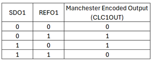
- Observe the output on logic
analyzer, it should follow the truth table as shown in the following
diagram: