3.6 Configuring SPI
Perform the following steps to configure the SPI of the ATWINC15x0.
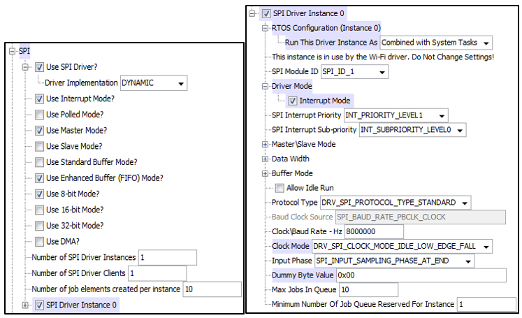
- Select the options to enable the SPI driver in interrupt mode under "SPI Driver Instance 0".
- Set the RTOS Configuration to Combined with System Tasks.
- Set the SPI Module ID to SPI_ID_1.
- Set the Clock Mode to IDLE_LOW_EDGE_FALL.
- Set the Dummy Byte value to 0x00.
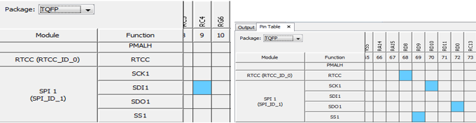
Based on the Microchip reference hardware – PIC32MX PIM and WINC1500 PICtail on the Explorer 16/32 Board, the configured SPI pin in the MHC Pin table are as follows:
| SPI Pin | Pin Number | Port |
|---|---|---|
| SCK1 | 70 | RD10 |
| SDI1 | 9 | RC4 |
| SDO1 | 72 | RD0 |
| SS1 | 69 | RD9 |