4.2.4 Configuring PIC24 MCU using MCC
The SPI, UART, Timer and external interrupt of the PIC24 MCU must be configured as described below using the MPLAB Code Configurator (MCC).
- Open MCC, then save the
MyConfig.mc3file to the root of the project.The pin mapping configuration of the MCC is stored in the
MyConfig.mc3file.Figure 4-16. Saving MyConfig.mc3 File to Root of the Project 
- From the “Device Resources” menu of
MCC, add the required modules, such as SPI, UART, Timer and external interrupt, to
the project.
Figure 4-17. System Module Configuration 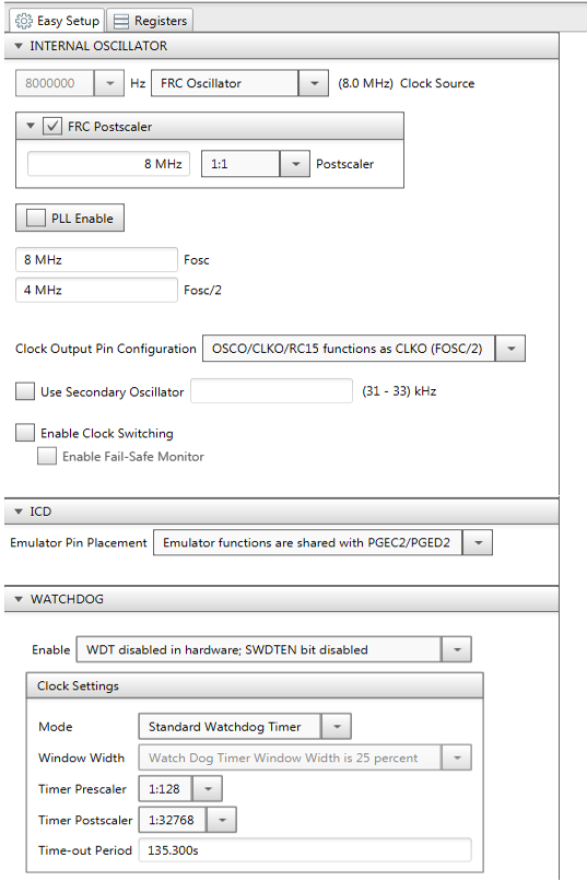
- SPI Configuration
The ATWINC15x0 PICtail plus module is connected to the J9 connector from pin 33 to pin 62. Therefore, set the SPI2 configuration parameters as shown in the following image. The PIC24 SPI works in the Master mode, and ATWINC15x0 works in the Slave mode.
Figure 4-18. SPI2 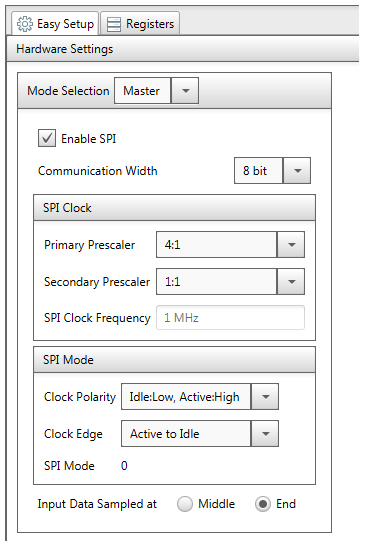
- UART Configuration
Set the UART configuration parameters as shown in the following image. The user can also set the UART baudrate as required.
Figure 4-19. UART2 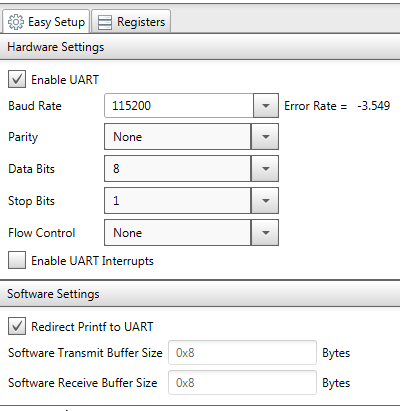
- Timer configuration
Set the Timer configuration parameters as shown in the following image. The Timer is used for generating a delay in the ATWINC15x0 driver.
Figure 4-20. TMR1 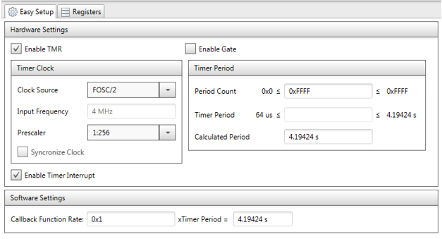
- External Interrupt configuration
Set the external interrupt configuration parameters as shown in the following image. The ATWINC15x0 uses the external interrupt for changing the notification. In this case, INT3 resource of PIC24 is used for generating a change in the notification.
Figure 4-21. EXT_INT 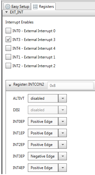
- Pin Manager Configuration
Based on the hardware design, the user needs to configure the pins of the different modules.
The external interrupt pin must be configured using the MCC pin manager grid view as follows.- Connect pin 18 of the ATWINC15x0 PICtail plus to pin 55 of the PICtail plus J9 connector.
- Map pin 55 of the J9 connector to pin 66 of the PIC24 PIM connector.
- Configure pin 66 (RA14) of the PIC24 for INT3 and configure the SPI, UART, ICD, GPIO pins based on the hardware design.
The pin mapping of PIC24 PIM and ATWINC15x0 PICtail plus is shown in the following pin manager grid view snapshot. The user only needs to modify the pin mapping in the pin mapping grid view.
Figure 4-22. Pin Manager Grid View 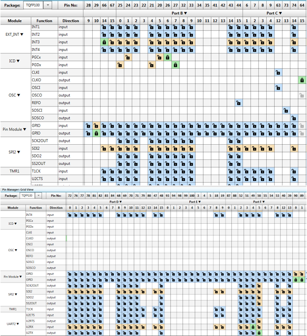
The pin module view shows the details of all of the pin mapping. The user can redefine the name of each of the modules. Based on the user-defined name, the MCC auto-generated modules enable/disable the functionality.
Figure 4-23. Pin Module 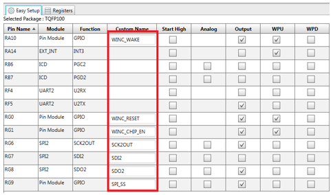
Similarly, user-defined names are updated in the pin manager package view, as shown in the following snapshot.
Figure 4-24. PIC24FJ128GA310 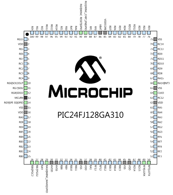
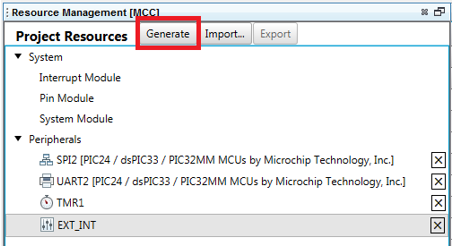
After adding all of the modules and configuring the pins based on the hardware design, click “Generate” to generate the code, as shown in the following snapshot.
Figure 4-25. Resource Management