3.1.3.2 CW
The following table provides the command syntax for CW TX mode.
| Command Syntax | MCHPRT 8 X Y Z A B C D L F | ||||
|---|---|---|---|---|---|
| X | X refers to TX channel: 1 to
14
| ||||
| Y Z | Y refer to Rate, Z refers to Preamble: | ||||
| Rate = 0 | Preamble = 0 | 11b | 1 Mbps | — | |
| Rate = 1 | Preamble = 0 | 11b | 2 Mbps | — | |
| Rate = 2 | Preamble = 0 | 11b | 5.5 Mbps | — | |
| Rate = 3 | Preamble = 0 | 11b | 11 Mbps | — | |
| Rate = 0 | Preamble = 1 | 11g | 6 Mbps | — | |
| Rate = 1 | Preamble = 1 | 11g | 9 Mbps | — | |
| Rate = 2 | Preamble = 1 | 11g | 12 Mbps | — | |
|
Rate = 3 | Preamble = 1 | 11g | 18 Mbps | — | |
| Rate = 4 | Preamble = 1 | 11g | 24 Mbps | — | |
| Rate = 5 | Preamble = 1 | 11g | 36 Mbps | — | |
| Rate = 6 | Preamble = 1 | 11g | 48 Mbps | — | |
| Rate = 7 | Preamble = 1 | 11g | 54 Mbps | — | |
| Rate = 0 | Preamble = 2 | 11n | MCS - 0 | 0x80 | |
| Rate = 1 | Preamble = 2 | 11n | MCS - 1 | 0x81 | |
| Rate = 2 | Preamble = 2 | 11n | MCS - 2 | 0x82 | |
| Rate = 3 | Preamble = 2 | 11n | MCS - 3 | 0x83 | |
| Rate = 4 | Preamble = 2 | 11n | MCS - 4 | 0x84 | |
| Rate = 5 | Preamble = 2 | 11n | MCS - 5 | 0x85 | |
| Rate = 6 | Preamble = 2 | 11n | MCS - 6 | 0x86 | |
| Rate = 7 | Preamble = 2 | 11n | MCS - 7 | 0x87 | |
| A | A refers to bandwidth: 0/1 – 20 MHz | ||||
| B | B refers to Digital Gain
(Bypass mode): Range: -20 to 0 DG: Dynamic Gain | ||||
| C | C refers to PA gain (Bypass
mode):
| ||||
| D | D refers to PPA gain (Bypass
mode):
| ||||
| L | L refers to length: 0 – 1500 Maximum limit is 1500 | ||||
| F | F mean Frequency offset : -50
to +50 base on Crystal XO: eFuse XO value | ||||
| Example | MCHPRT 8 1 7 2 0 -10 18 6
1500 0 Channel 1. MCS 7 – 20 MHz, length 1500, 0 ppm offset DG – 10, PPA 6, PA 18 CW mode | ||||
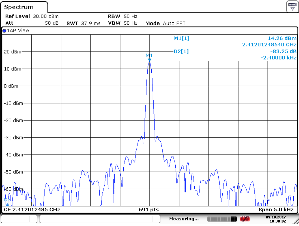
The following figure shows the example of start CW TX mode.


The CW TX mode starts as shown in the following figure.