
1.2 Enhanced Receiver Management
(Ask a Question)Enhanced Receiver Management (ERM) is implemented in FPGA logic inside the XCVR component. The ERM adds DFE/CDR calibration management, and lock-to-data lock detection capabilities of the XCVR component. The RTL is automatically generated by Libero software. The generated blocks manage the start-up/on-demand CDR/DFE calibration and fine-grain lock detector using PMA, 8b10b, and 64b6xb modes of the XCVR component. The ERM enables the Rx Lock detection logic to handle advanced capabilities of Delayed Traffic and Cable Pull during operation without further interaction from other user logic.
The enhanced receiver management feature provides the following functions.
- Manages receiver lock-to-reference versus lock-to-data operation modes of XCVR component.
- Manages receiver calibration, see Receiver Calibration.
- Provides optional automatic calibration upon determining first valid receiver bit-lock.
- Provides optional support for on-demand requested calibration.
- Provides optional support for Data Eye clock centering recalibration.
- Provides optional support for DFE Coefficient recalibration.
- Provides indicator when receiver completes calibration.
- Provides LANEx_LOS input, which may be asserted as a means of holding lock management in lock-to-reference. This is useful when interfacing to an optical interface, which provides a loss-of-signal indicator such as SFP.
Enhanced receiver management is recommended to optionally improve the link management for high data rates but can be used to improve link reliability with lower data rates while using the automatic calibration features of ERM. Enhanced receiver management is not included for PCI Express, PIPE, or Burst Mode Receiver solutions of PF_XCVR when generated by Libero software. Generally, the advanced features from ERM are already managed by these protocol layers.
ERM is utilized to augment the Rx_IDLE peak detector logic, which is only valid for a limited minimum density of transitions on the Rx data or high bit rates. Other lower density patterns such as SDI at 270 Mbps or 10G-KR Auto-negotiation data are good examples of data patterns that cannot use the peak detector and thus other system-dependent methods to keep the Rx PLL in lock-to-reference mode in the absence of incoming data are required.
For example, some protocols such as PCI-Express, exchange specific training patterns to establish and tune the respective links. These protocols does not use the ERM as it can interfere with these kinds of negotiation operations. Other applications such as CPRI goes through a sophisticated process by stepping through multiple data rates during its startup. The ERM must not be used in this type of application. ERM must also not be used with Rx-only modes such as DisplayPort where the RxPLL is locked to a lower rate data stream.
ERM can be used with JESD204b, Interlaken, and fixed rate CPRI applications. ERM is not recommended for data rates of 6 Gbps or lower for 8b10b balanced data streams. These data rates are supported natively using the built-in signal detection circuitry not requiring the ERM. Unnecessary use of the ERM for slower data rates can interfere with proper operation of the native clock-data recovery of the transceiver.
The ERM uses minimal logic resources, but does extend the lock time of the CDR by approximately three times versus when the ERM is not included.
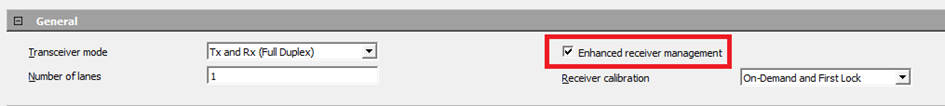
The ERM ports are exposed by the transceiver configurator dependent on the selected calibration when enabled (default) in the GUI, see Figure 1. If the XCVR module is generated without selecting the ERM option in the Libero SoC configurator, the module will still contain ERM in the component name, however, the ERM functionality is removed. The following table lists the ports required or used in conjunction with the ERM module.
| Name | Direction | Description |
|---|---|---|
| CTRL_CLK | Input | 40 MHz clock for the enhanced receiver management logic. The CTRL_CLK input clock can be sourced from the divided output of the PF_OSC (RCOSC_160MHZ_CLK_DIV). |
| CTRL_ARST_N | Input | Input signal needed to reset ERM. User must drive this input from the XCVR_INIT_DONE signal of the PF_INIT_MONITOR component. |
| LANE#_LOS | Input | LANEx_LOS input which may be asserted from an external source such as optical SFP during no-signal condition as a means of preventing entry to lock-to-data. This input must be used to control application scenarios where the incoming data stream has enough activity to trigger the LANE#_RX_IDLE but lacks enough transitions to lock the RXPLL. LOS=0 (de-assertion) must occur when valid serial data is applied at the RxP/N inputs of the receiver. LOS=1 assertion must happen prior to the ERM's entry to lock-to-data, otherwise the assertion does nothing. |
| LANE#_CALIB_REQ | Input | Active-high input signal used to request an On-Demand calibration. LANE#_CALIB_REQ is edge triggered not level. User must clear and re-assert the CALIB_REQ for trigger on-demand calibration request. |
| LANE#_CALIBRATING | Output | Output signal that will go HIGH to indicate that the DFE/CDR is calibrating. |
| LANE#_RX_VAL | Output | Indicates CDR fine lock and ERM managed
operations complete. See Transceiver PCS Interface Modes for
more information. 1 – indicates Fine Lock is asserted, and recovered data is valid. 0 – indicates Fine Lock is de-asserted and recovered data is invalid. |
| LANE#_RX_IDLE | Output | Indicates activity on the receiver inputs (RXD[P:N]). For ≤ 5 Gbps, active-low (RX_IDLE=0 indicates activity). For >5G bit rates, this signal may not be accurate indicator of data activity. It may toggle or be HIGH although valid signal is applied at the receiver. This signal is exposed for debugging purposes only, for example, detection of signal when RxPLL is in lock2ref mode. See Figure 5, Figure 6, Figure 7, and Figure 8. |
| LANE#_RX_READY | Output | Indicates CDR fine lock completion. See
Transceiver PCS Interface Modes for
more information.
1 – Fine lock is asserted (that is, RxPLL is locked to
incoming data within
± 4000 ppm of the LANE#_TX_CLK_{G,R} frequency). 0 – Fine lock is de-asserted (that is. recovered clock is outside the ± 4000 ppm of the REFCLK frequency). |
| LANE#_RXD[P:N] | Input | Differential pair of serial data inputs. |
| LANE#_DATA_EYE_ CALIBRATION | Input | Active-high input signal (Asynchronous signal) to request Data Eye clock centering recalibration. |
| LANE#_DFE_COEFF_CALIBRATION | Input | Active -high input signal (Asynchronous signal) to request Incremental DFE Coefficient recalibration. |
| LANE#_DATA_EYE_ CALIBRATION_DONE | Output | Data Eye clock centering recalibration request handshake signal. This signal goes high when the Data Eye clock centering calibration is done. |
| LANE#_DFE_COEFF_CALIBRATION_DONE | Output | Incremental DFE coefficient recalibration request handshake signal. This signal goes high when the Incremental DFE coefficient recalibration is done. |
The operation ERM relies on the transceiver configurator settings to determine the selected calibration requirements, as shown in the following figure. The transceiver lane calibration options are selected with the transceiver configurator. See Receiver Calibration for more information.

The following receiver calibration options are provided for the ERM operation:
- None (CDR): Select if the XCVR is configured as CDR and no CTLE auto-calibration is performed. Static settings are configured by Libero based on data rate and backplane model. This receiver calibration mode uses Lock2Reference of the Rx PLL.
- On-Demand and First Lock: Select to perform calibration on first lock (after PoR) and on-demand. This option is available for both CDR and DFE configuration of the XCVR. You can trigger calibration on-demand using CALIB_REQ port. The CALIBRATING signal is asserted upon CALIB_REQ assertion and de-asserted when the calibration is completed.
- On-Demand: Select to perform calibration on-demand. This option is available for both CDR and DFE configuration of the XCVR. You can trigger calibration on-demand using CALIB_REQ port. The CALIBRATING signal is asserted upon CALIB_REQ assertion and de-asserted when the calibration is completed.
- None (Static DFE): DC Offset Calibration of the CDR is performed, however, the DFE Coefficients are set through PDC commands used from the register rather than from automatic DFE calibration operation. See Physical Constraints. Static_DFE does not use the DFE calibration routine and requires the user to carefully select DFE coefficient values. These values can be gathered by the SmartDebug tool or by simulation.
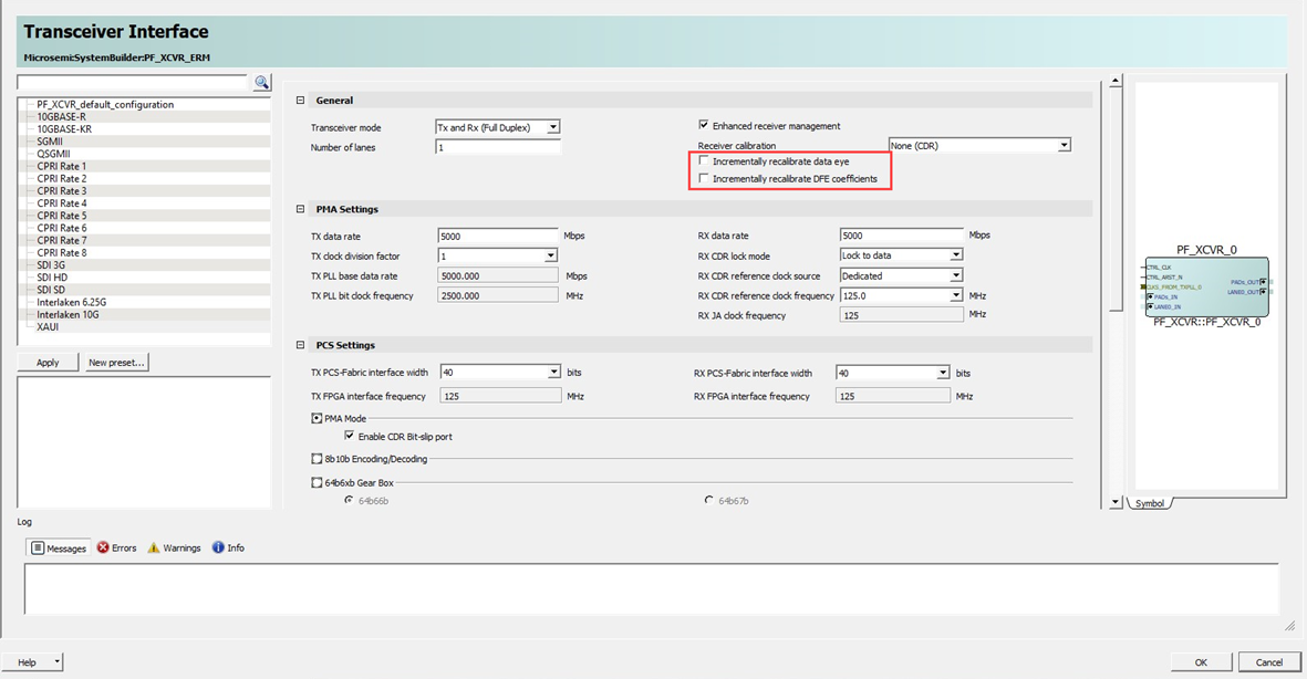
There are two potential ways to incrementally improve the performance of the DFE path when an initial calibration is completed.
- Incrementally Recalibrate Data Eye: This recalibration should improve the data eye for most gradients that typically occur from temperature or voltage changes within the system.
- Incrementally Recalibrate DFE Coefficient: This recalibration performs the DFE calibration in incremental method. The initially calculated DFE coefficient values are used as the starting values for this algorithm. This results in the reduction of the Calibration time by reducing the number of DFE coefficients that requires recalibration.
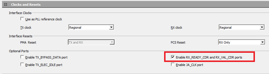
Enable LANE#_RX_READY_CDR and LANE#_RX_VAL_CDR ports are optionally exposed by selecting the associated checkbox for the ERM solution. The XCVR component provides optional RX_READY_CDR and RX_VAL_CDR ports for the datapath and variation of the LANE#_RX_READY and LANE#_RX_VAL ports that are always exposed with the ERM. These additional ports are provided to monitor the CDR lock signal. These ports can be used for rate change from >5G to <5G and 10GBASE-KR auto-negotiation support.
XCVR designs implementing protocols with auto-negotiation logic typically negotiates link rates over DRI. In these use cases, the ERM will interfere with the auto-negotiation and can cause incorrect behavior.
The ERM manages the device behavior at first power-up or release from device reset (DEVRSTn). The ERM managed calibration begins after the device complete its initial startup configuration and the assertion of XCVR_INIT_DONE de-asserts the CTRL_ARST_N. This requires a valid serial data stream to be applied to the RXD input pins at the time of de-assertion of the CTRL_ARST_N signal. At that time, the ERM performs the desired user selected calibration operation as shown in the following figure. The LANE#_RX_IDLE activity shows the detection of incoming data moving the ERM to place the CDR into LOCK2DATA operation while it completes calibration and fine lock operation. The operation is indicated by the LANE#_CALIBRATING and RX_READY status signals. The LANE#_RX_VAL with output high upon completion of the calibration and locking routine.
The following table lists the ports exposed based on DFE options.
| Options | Input Port | Output Port |
|---|---|---|
| Incrementally recalibrate data eye | LANE#_DATA_EYE_CALIBRATION | LANE#_DATA_EYE_CALIBRATION_DONE |
| Incrementally recalibrate DFE coefficients | LANE#_DFE_COEFF_CALIBRATION | LANE#_DFE_COEFF_CALIBRATION_DONE |
The following waveforms show the behavior of the XCVR with ERM optionally included in the Libero generated component. XCVR configurations without ERM operates with reduced functionality and the LANE#_RX_READY behavior is identical to the LANE#_RX_READY_CDR waveform since the ERM no longer manages the lane.

During data transmission if the serial link is disrupted due to lack of activity detected by the Fine Lock LANE#_RX_READY = 0 and toggling of the LANE#_RX_IDLE output signal, the ERM handles a switch over of the CDR from LOCK2DATA to LOCK2REF as shown in the following figure. The ERM manages this mode until the data stream is re-established or the transceiver is placed into reset.

The ERM manages the re-establishment of a link after a break or disruption. A restart begins when a valid data stream is re-applied to the receiver inputs. This starts the operation of the ERM to systematically control the CDR to re-initialize the link. As shown in the following figure, the ERM properly re-establishes a CDR fine lock after assuring the link is stable. When the link polling is complete, the ERM transitions the transceiver back to proper operation. This is completed without changing any of the CDR or DFE calibration settings and returns calibration setting to those used prior to the disruption or break in the serial data stream.

The user can also optionally invoke a calibration on-demand. This would be needed if the interconnection is changed such as swapping cables or other interface media. In this case, the user can request calibration only after a valid data stream is applied to the RXD inputs. As shown in the following figure, assertion of the LANE#_CALIB_REQ initiates the ERM to invoke a CDR/DFE calibration during which the CDR remains LOCK2DATA. The LANE#_CALIB_REQ is required to stay asserted by the user logic until LANE#_CALIBRATING goes HIGH.

The ERM can be optionally not included at design creation using the Libero transceiver configurator. Transceiver designs that do not include the ERM have to manage the before mentioned considerations and should only be not used after carefully understanding the system requirements. Without the ERM, the transceiver LANEx_RX_READY pin may toggle when the Rx signal is open or disconnected, or while an out-of-range condition occurs. For example, incorrect Rx serial data rates, with serial input data >1.17% away, is considered out of range.
Initially, the Rx CDR lock may not lock with missing or bad data stream. The following conditions prevent the incorrect behavior.
- The Rx data rate is <±300 ppm of the Libero configured rate.
- Rx data is present when PMA_ARST is de-asserted.
- Data stream must not stop once locked or the CDR Lock circuitry might not properly indicate the status of the CDR.
- PMA_ARST can be used to restart with any data stream disruptions.