
5 Step by Step Guide
Detailed instructions for each provisioning step from key generation through device programming.
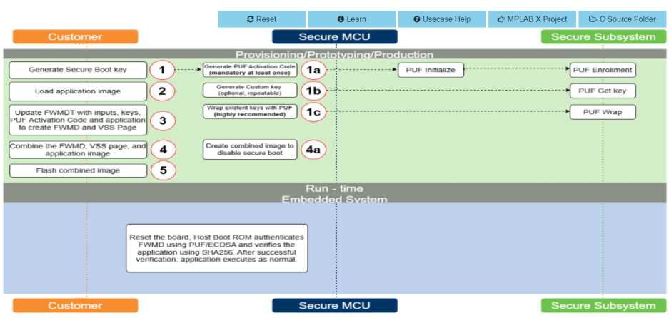
Step 1: Generate / Load Secure Boot Key
| Method | generate_resources |
| Prerequisite | None (first step) |
| Repeatable | No -- slot 2 is fixed; shows warning if already loaded |
What it does:
-
Connects to the Secure Element via USB HID kit-protocol.
-
Discovers the HSMLITE device on the board. If the factory kit firmware is not programmed, it programs it automatically and asks the user to reset the board.
-
Generates or loads an ECC P-256 key pair for firmware signing.
-
Registers the key in VSS slot 2 (the HSM secure boot signing slot -- fixed, not user-selectable).
Key generation dialog:
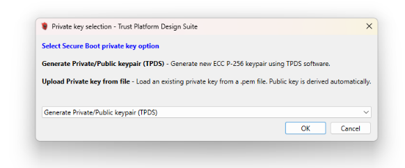
| Option | Description |
|---|---|
| Generate Private/Public keypair (TPDS) | Creates a new ECC P-256 key
pair using the TPDS TPAsymmetricKey library (software
generation) |
| Upload Private key from file | Loads an existing private
key from a .pem file. The public key is derived
automatically. |
Output files:
| File | Content |
|---|---|
private_key_slot2.pem | ECC P-256 private key (PKCS#8 PEM) |
public_key_slot2.pem | ECC P-256 public key (SubjectPublicKeyInfo PEM) |
Step 1a: PUF Enrollment
| Method | puf_enrollment |
| Prerequisite | Step 1 (board must be connected) |
| Repeatable | Yes, but only needed once per device |
What it does:
-
Requests a PUF Activation Code (996 bytes) from the PUF hardware via the kit-protocol command.
-
Saves the activation code as
PIC32CMSG_PUF_AC.hex(Intel HEX format) at address0x0A003C00.
PUF enrollment only needs to be performed once per device. If the PUF has already been enrolled (the hex file exists), a dialog will inform the user and ask whether to re-enroll.
Automatic PUF AC reload: If Step 1b or 1c is executed later without Step 1a having run in this session, the tool will automatically:
-
Load the PUF AC from the saved
PIC32CMSG_PUF_AC.hexfile. -
Send it to the device via the kit-protocol command.
-
Verify the echoed response matches the original data.
Step 1b: Generate / Load Additional User Keys (Repeatable)
| Method | generate_user_key |
| Prerequisite | Step 1 (board must be connected) |
| Repeatable | Yes -- up to 10 keys total (including the Step 1 key) |
What it does:
Adds additional keys to the internal key registry. Each execution adds one key. This step presents a two-level dialog:
First dialog: PUF or not?
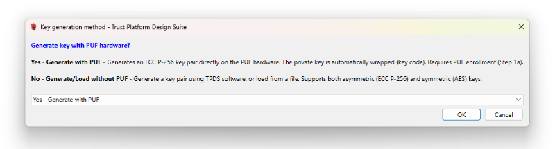
| Option | Description |
|---|---|
| Yes - Generate with PUF | Generates an ECC P-256 key pair. PUF generates a key which is considered a "private" key. This "private" key is sent to the TPDS software and the public key is then derived from it by TPDS using ECC algorithm. Requires Step 1a (PUF enrollment). Wrapping is NOT done here -- it is deferred to Step 1c. |
| No - Generate/Load without PUF | Opens the key-type selection dialog (see below). Supports both asymmetric and symmetric keys, generated via software or loaded from file. |
Second dialog (non-PUF path): Key type selection.
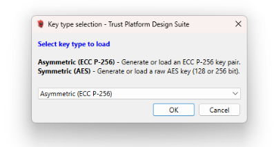
| Option | Description |
|---|---|
| Asymmetric (ECC P-256) | Generate a new key pair with
TPDS software, or load from a .pem file |
| Symmetric (AES) | Load a raw AES-128 or AES-256 key. Sub-dialog asks for key size, then input method (file or manual hex entry). |
Third dialog: Slot index.
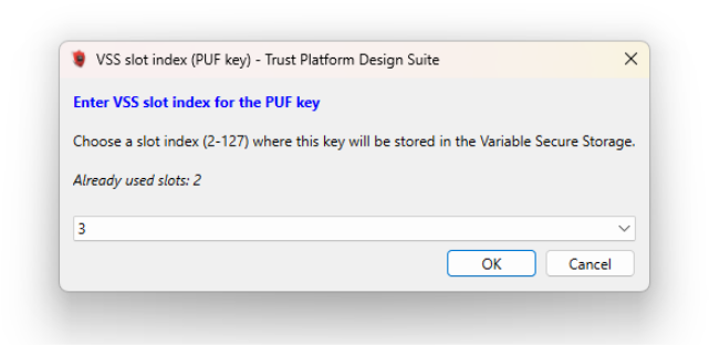
After selecting the key type, the user is asked to choose a VSS slot index (2-127) where this key will be stored. The dialog shows which slots are already in use. Duplicate slots are rejected.
Output files (per key):
| Key Type | Files Generated |
|---|---|
| Asymmetric (TPDS) | private_key_slot{N}.pem,
public_key_slot{N}.pem |
| Asymmetric (PUF) | private_puf_key_slot{N}.pem,
public_puf_key_slot{N}.pem |
| Symmetric (AES 128) | symmetric_key_slot{N}_aes128.pem |
| Symmetric (AES 256) | symmetric_key_slot{N}_aes256.pem |
Example session (loading 3 keys):
Click 1b -->  "No - Generate/Load without PUF"
              "Asymmetric (ECC P-256)"
              Slot: 3
              "Generate Private/Public keypair (TPDS)"
              --> Key registered in slot 3

Click 1b -->  "Yes - Generate with PUF"
              Slot: 5
              --> PUF key generated, registered in slot 5

Click 1b -->  "No - Generate/Load without PUF"
              "Symmetric (AES)"
              "AES-256 (32 bytes)"
              Slot: 10
              "Load from hex file"
              --> AES-256 key registered in slot 10
After these 3 executions plus Step 1, the registry contains 4 keys (slots 2, 3, 5, 10).
Step 1c: Wrap All Keys With PUF
| Method | puf_wrap_all_keys |
| Prerequisite | Step 1a (PUF enrollment must be completed) |
| Repeatable | Yes (idempotent -- skips already-wrapped keys) |
What it does:
Iterates the entire key registry and wraps every key that does not already have a key code, using the PUF hardware via the kit-protocol command.
Wrapping rules:
| Key Type | What Gets Wrapped | Key Code Field |
|---|---|---|
| Asymmetric | Private key only (public key can be derived) | keycode_prv |
| Symmetric | Full key data | keycode |
Skip conditions (per key):
-
Already has a key code (
keycode_prvorkeycodeis not None) -
No key material available (e.g., private key is None)
Key code slot convention (demo only):
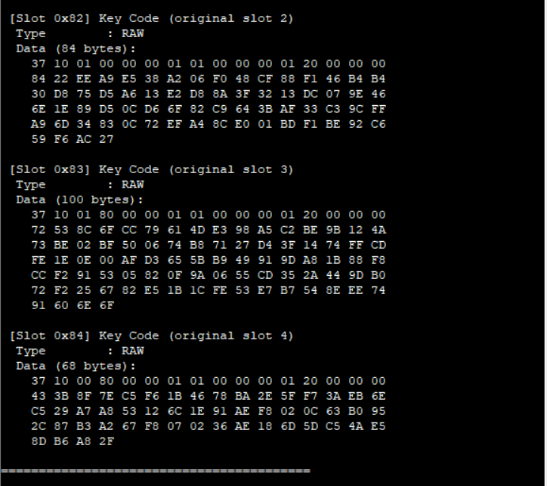
keycode_slot = 0x80 | original_slot
-
Bit 7 (0x80) = key code flag
-
Bits [6:0] = original slot index
0x80 |
          original_slot
convention is used for demonstration purposes only, so that the LED
demo application provided in this use case can locate and unwrap key codes to compare them
against the original keys. In a production deployment, slots 3-255 are freely available for
both keys and key codes, and users can assign any slot number according to their own
requirements.Example: A key in slot 5 produces a key code in slot 0x85 (133).
Output files: For each wrapped key in slot N:
| Key Type | File |
|---|---|
| Asymmetric (private key) | slot{N}_privkey_keycode.txt |
| Symmetric | `slot{N}_{aes128 |
Console output example:
STEP 1c: Wrap all registered keys with PUF
  Slot   2: Wrapping private key (ECC P-256 (GEN_TPDS_PRVKEY))...
           Key code saved to slot2_privkey_keycode.txt
  Slot   3: Wrapping private key (ECC P-256 (GEN_TPDS_PRVKEY))...
           Key code saved to slot3_privkey_keycode.txt
  Slot   5: Wrapping private key (PUF ECC P-256 Key Pair)...
           Key code saved to slot5_privkey_keycode.txt
  Slot  10: Wrapping symmetric key (AES256 key)...
           Key code saved to slot10_aes256_keycode.txt

Wrap summary: 4 wrapped, 0 skipped
  Slot   2: ECC P-256 (GEN_TPDS_PRVKEY) [wrapped]
  Slot   3: ECC P-256 (GEN_TPDS_PRVKEY) [wrapped]
  Slot   5: PUF ECC P-256 Key Pair [wrapped]
  Slot  10: AES256 key [wrapped]
Executed Step 1c Successfully
If executed again (idempotent):
STEP 1c: Wrap all registered keys with PUF
  Slot   2: ECC P-256 (GEN_TPDS_PRVKEY) -- already wrapped, skipping
  Slot   3: ECC P-256 (GEN_TPDS_PRVKEY) -- already wrapped, skipping
  Slot   5: PUF ECC P-256 Key Pair -- already wrapped, skipping
  Slot  10: AES256 key -- already wrapped, skipping

Wrap summary: 0 wrapped, 4 skipped
Key code size depends on the key length:
| Key Type | Key Length (bytes) | Key Code Size (bytes) |
|---|---|---|
| ECC P-256 private | 32 | 84 |
| AES-128 | 16 | 68 |
| AES-256 | 32 | 84 |
Formula: keyCodeSize = 36 + keyLen + 16 * ceil(keyLenBits / 384).
Step 2: Load Application Image
| Method | load_custom_application |
| Prerequisite | Step 1 |
| Repeatable | Yes (replaces previous selection) |
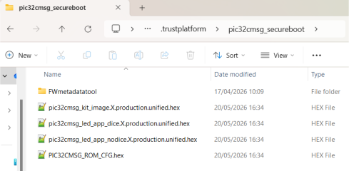
~/.trustplatform/pic32cmsg_secureboot/):pic32cmsg_led_app_dice.X.production.unified.hex— Device Identifier Composition Engine (DICE) enabled (Compound Device Identifier (CDI) and FW Hash shown on console)pic32cmsg_led_app_nodice.X.production.unified.hex— DICE disabled (standard demo)
Both are built from the same source code with different fuse configurations
(BOOT_FLAG_DICEDIS = CLEAR vs. SET). They both demonstrate secure boot,
PUF key verification, and VSS keystore reading.
What it does:
-
Opens a file dialog to select a custom application
.hexfile. -
Extracts per-region hex slices (Boot ROM, Boot Config) from the selected hex file.
-
Prepares the hex file segments for the FWMDT.
The user can select any compatible application hex file. The LED demo variants above are provided as reference and validation tools.
Regions extracted:
| Region | Address Range | Skip Logic |
|---|---|---|
bootrom | 0x08000000 -
0x08003FFF | Extracted from app hex |
bootcfg1 | 0x0A002800 -
0x0A002FFF | Start shifted +0x800 to skip FWMD area |
bootcfg1a | 0x0A000800 -
0x0A000FFF | Start shifted +0x800 to skip FWMD area |
romcfg | Skipped | Uses template (DAL = 2) |
pufac | Skipped | Generated by Step 1a |
app | Skipped | Full hex used directly |
Step 3: Execute Firmware Metadata Tool
| Method | execute_fwmdt |
| Prerequisite | Steps 1, 1a, and 2 |
| Repeatable | Yes |
What it does:
-
BOOTCFG region selection: prompts for the region where the FWMD will be placed:
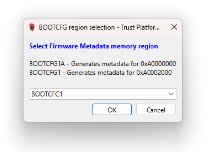
Region FWMD Address BOOTCFG Address BOOTCFG1 (default) 0x0A0020000x0A002800BOOTCFG1A 0x0A0000000x0A000800 -
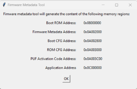
Memory region summary: displays a window showing all addresses that will be included in the metadata.
-
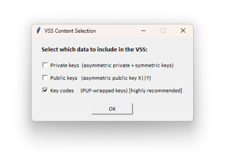
VSS content selection: displays a checkbox dialog (see VSS Content section) to choose which key material to include in the VSS.
-
Updates XML files: populates
PIC32CMSG_fwmd.xml(image addresses and file paths) andPIC32CMSG_sfp.xml(signing key, VSS variable slots) from the key registry. -
Runs
hsmsfmdgen.exe: computes SHA-256 hashes of all image segments, signs the FWMD with the signing key (slot 2), and generates the output hex files.
Output files:
| File | Description |
|---|---|
pic32cmsg_fwmd.hex | Combined image: FWMD + Boot ROM + Boot Config + ROM Config + PUF AC + Application |
pic32cmsg_sfp.hex | VSS data consumed by the ROM Boot process |
Step 4: Combine Images
| Method | combine_images |
| Prerequisite | Step 3 |
| Repeatable | Yes |
What it does:
Merges pic32cmsg_fwmd.hex and pic32cmsg_sfp.hex into a
single file: pic32cmsg_secure_boot.hex using
IntelHex.merge(overlap='error').
This combined hex is ready to be programmed onto the device.
Step 4a: Disable Secure Boot (Optional)
| Method | disable_secureboot |
| Prerequisite | Step 3 |
| Repeatable | Yes |
What it does:
-
Modifies the SFP XML to set:
-
lifecycleState = open. -
secureBootConfiguration = disabled.
-
-
Regenerates the FWMD and SFP hex files.
-
Combines them into
pic32cmsg_secure_boot_disabled.hex.
This is useful for development and debugging when signature verification is not desired.
- DICE runs as part of the secure boot chain
- The generation of the UDS/CDI and derived identities only happens when the Boot ROM enters the Secure Boot flow
Step 5: Program Device
| Method | program_device |
| Prerequisite | Step 4 |
| Repeatable | Yes |
What it does:
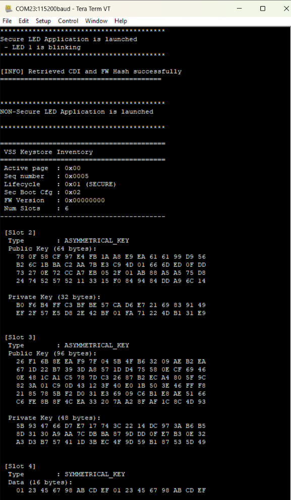
Programs the combined hex image (pic32cmsg_secure_boot.hex or the disabled variant) onto the PIC32CMSG00 device using MPLAB X IPE (FlashProgram). After programming, the device will reset and the Boot ROM will perform the secure boot sequence.
Expected Output (LED Demo Application with DICE enable).
After Step 5 completes successfully with the LED demo application
(pic32cmsg_led_app_dice.X.production.unified.hex), the following behavior
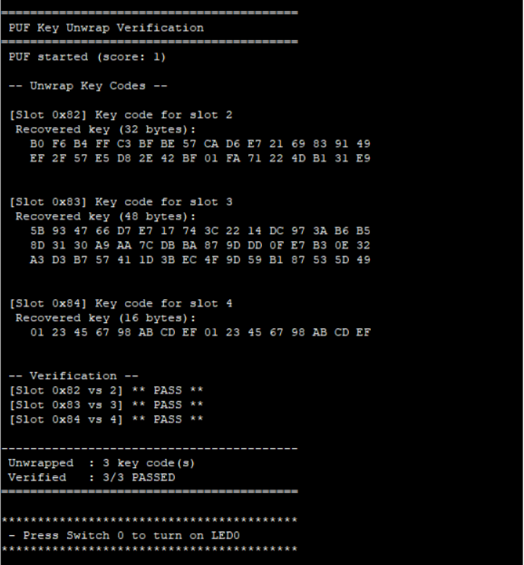
confirms a successful provisioning:
Board behavior:
-
The board resets automatically after programming completes
-
LED1 blinks (heartbeat indicating the application is running)
-
SW0 button press turns on LED0
Serial terminal output (115200-8-N-1):
Reprogramming a Secured Device
If Step 4a was not executed (secure boot remains enabled), the device will enforce signature verification on every boot. This section explains how to reprogram or recover the board.
Reprogram with a New Application Image.
The signing key is preserved across sessions in the project output folder as
private_key_slot2.pem. To update the application:
-
Re-run Step 2 with the new application
.hexfile. -
Re-run Steps 3> 4>5 (using the same signing key from Step 1).
The new image will be signed with the same key and the device will accept it.
Return to Unsecured State (Factory Reset).
To completely remove secure boot and return the device to an open state:
-
Open MPLAB X IPE (or use the debugger).
-
Perform a Chip Erase operation.
-
This erases all Flash including FWMD, VSS, and Boot Configuration.
-
The device returns to DAL = 2 (open/unsecured) state.
-
The user can reprogram the board with any unsigned image.
Summary:
| Situation | Action | Result |
|---|---|---|
| Update app with same key | Re-run Steps 2>3>4>5 | New signed image boots normally |
| Lost the signing key | Chip Erase via MPLAB X IPE | Device returns to open state |
| Want to disable secure boot | Run Step 4a, then Step 5 | Device boots without verification |
| Board appears bricked | Chip Erase via MPLAB X IPE | Full recovery, DAL = 2 restored |