
14 LED Demo Application
Overview
The LED demo application (pic32cmsg_led_app) is a TrustZone dual-world firmware that demonstrates the PIC32CMSG00 secure boot flow. It exercises VSS keystore reading, PUF key unwrap/verification, and basic GPIO control across the TrustZone boundary.
The application is distributed as two .hex variants, both containing the Secure and Non-Secure images ready to be programmed alongside the FWMD and VSS data:
pic32cmsg_led_app_dice.X.production.unified.hex— DICE enabled (CDI and FW Hash: read values and report the result of the read operation)pic32cmsg_led_app_nodice.X.production.unified.hex— DICE disabled (standard demo)
Both are built from the same source code with different fuse configurations
(BOOT_FLAG_DICEDIS = CLEAR vs. SET).
Software Architecture

Memory Map
| Region | Address | Size | Description |
|---|---|---|---|
| Secure Flash (PFM) | 0x00000000 | Variable | Secure application code |
| Non-Secure Flash | 0x0C040000
(TZ_START_NS) | 256 KB | Non-Secure application code |
| Non-Secure Callable (NSC) Region | - | 4 KB | NSC veneers |
| VSS Page 0 | 0x0A004000 | 4 KB | VSS (active) |
| VSS Page 1 | 0x0A005000 | 4 KB | VSS (backup) |
| PUF Activation Code | 0x0A003C00 | 996 B | PUF Enrollment data |
| Non-Secure RAM | - | 64 KB | Non-Secure data/stack |
Secure Project (pic32cmsg_led_app_secure/src/)
| File | Purpose |
|---|---|
main.c | Secure entry point: init peripherals, start SysTick (LED1 blink), launch NS |
vss_keystore.c | VSS Flash page read-only accessor functions |
vss_keystore.h | Complete VSS data structures and API declarations |
trustZone/nonsecure_entry.c | NSC veneer implementations (dump keys, verify, print) |
crypto/puf04891_pic32cmsg/drv_puf.h | PUF hardware driver API |
config/default/initialization.c | Peripheral initialization (PORT, CLOCK, SYSTICK, SERCOM4) |
config/default/stdio/xc32_monitor.c | printf() redirect to SERCOM4 USART |
Non-Secure Project (pic32cmsg_led_app/src/)
| File | Purpose |
|---|---|
main.c | Non-Secure entry: SYS_Initialize + super loop calling SYS_Tasks |
app.c | Application state machine: dump, verify, button/LED polling |
app.h | APP_STATES enum, APP_DATA struct |
trustZone/nonsecure_entry.h | Extern declarations for NSC functions |
config/default/bsp/bsp.c | BSP_Initialize: LED0 off at start |
config/default/bsp/bsp.h | LED0 (PA20), SWITCH0 (PB7), SWITCH1 (PB11) macros |
config/default/tasks.c | SYS_Tasks dispatcher - APP_Tasks() |
Non-Secure Side Initialization
The Non-Secure project has minimal initialization:
BSP_Initialize(): Sets LED0 off at startupAPP_Initialize(): Sets initial state toAPP_STATE_DUMP_KEYSNVIC_Initialize(): Configures NS interrupt controller
No clock or peripheral configuration on the NS side, all hardware initialization is handled by the Secure world before the NS jump.
Boot Sequence
- Reset: Cortex-M23 loads Secure MSP from
0x00000000, jumps to Secure Reset_Handler. - Secure
main():- DICE:
tram_read_dice_values()- reads CDI and FW Hash from TRAM (before SYS_Initialize, to preserve TRAM contents) - Initializes PORT, CLOCK, EVSYS, TRAM, SYSTICK, PM, SERCOM4, NVIC
- Prints boot banner to serial console
- Prints DICE result status (success, disabled, or error)
- Registers SysTick callback - toggles LED1 on every tick
- Starts SysTick timer
- Reads Non-Secure MSP from
TZ_START_NS(0x0C040000) - Sets Non-Secure MSP, reads NS Reset_Handler, jumps to it
- DICE:
- Non-Secure
main():- Calls
SYS_Initialize()- BSP_Initialize (LED0 off) + APP_Initialize - Enters infinite loop calling
SYS_Tasks()-APP_Tasks()
- Calls
APP_Tasks()state machine:APP_STATE_DUMP_KEYS: Callssecure_vss_dump_keys()(NSC)APP_STATE_VERIFY_KEYS: Callssecure_vss_verify_puf_keys()(NSC)APP_STATE_SERVICE_TASKS: Polls SW0 - LED0 on/off (loops forever)
DICE Support
The application supports DICE, which provides a hardware-rooted device identity based on firmware measurement. When enabled via fuses, the Boot ROM computes a CDI and stores it in TRAM for the secure application to retrieve.
How it works:
- The Boot ROM reads the
DICEDISfuse. If clear (0), DICE is enabled. - The PUF generates a Unique Device Secret (UDS).
- The Boot ROM computes: CDI = HMAC-SHA256(UDS, FW_measurement).
- CDI (32 bytes) is stored in TRAM at the index configured by
DICE_CDI_INDEXfuse. - FW Hash (32 bytes) is stored in TRAM at the index configured by
DICE_FW_HASH_INDEXfuse. - Boot ROM sets
DSU_BCC[1] =
            0x00000004
to signal successful boot completion. - The secure application reads CDI and FW Hash from TRAM before
SYS_Initialize().
Fuse configuration:
| Fuse | Value | Description |
|---|---|---|
BOOT_FLAG_DICEDIS | CLEAR (0) | DICE enabled |
DICE_CDI_INDEX | 0x20 | TRAM index for CDI (8 consecutive words) |
DICE_FW_HASH_INDEX | 0x10 | TRAM index for FW Hash (8 consecutive words) |
TRAM data format:
| Item | Type | Size | TRAM Index |
|---|---|---|---|
| CDI | uint32_t[8] | 32 bytes (256 bits) | 0x20 |
| FW Hash (firmware measurement) | uint32_t[8] | 32 bytes (256 bits) | 0x10 |
Console output (DICE enabled and successful):
[INFO] Retrieved CDI and FW Hash successfully
========================================
Console output (DICE disabled):
[INFO] DICE is disabled
========================================
Error conditions:
[ERROR] Boot sequence not complete-DSU_BCC[1]!= 0x04; Boot ROM did not finish DICE computation[ERROR] DICE enabled but CDI of FW Hash index invalid- Fuse indices are 0x7F (unconfigured)
SYS_Initialize() because TRAM contents may be affected by peripheral initialization. The DICE-enabled variant is pic32cmsg_led_app_dice.X.production.unified.hex; the DICE-disabled variant is pic32cmsg_led_app_nodice.X.production.unified.hex.Hardware Mapping
| Pin | Function | Behavior |
|---|---|---|
| LED1 (Secure) | SECURE_LED1 | Blinks autonomously via SysTick ISR |
| PA20 (Non-Secure) | NONSECURE_LED0 | Mirrors SW0 state (active-low) |
| PB7 | NONSECURE_SWITCH0 | Push-button (pressed = 0) |
| PB11 | NONSECURE_SWITCH1 | Push-button (pressed = 0, unused in demo) |
NSC Interface
All sensitive operations are performed entirely within the Secure world. The Non-Secure application calls them via veneer functions:
/* Print a message through secure UART (SERCOM4) */
void secure_print_msg(const char *msg);

/* Read and print the VSS keystore inventory to serial console */
void secure_vss_dump_keys(void);

/* Unwrap PUF key codes, compare against originals, print PASS/FAIL */
void secure_vss_verify_puf_keys(void);
Security property: No key material ever crosses the TrustZone boundary. All data is printed to the serial console directly from the Secure world.
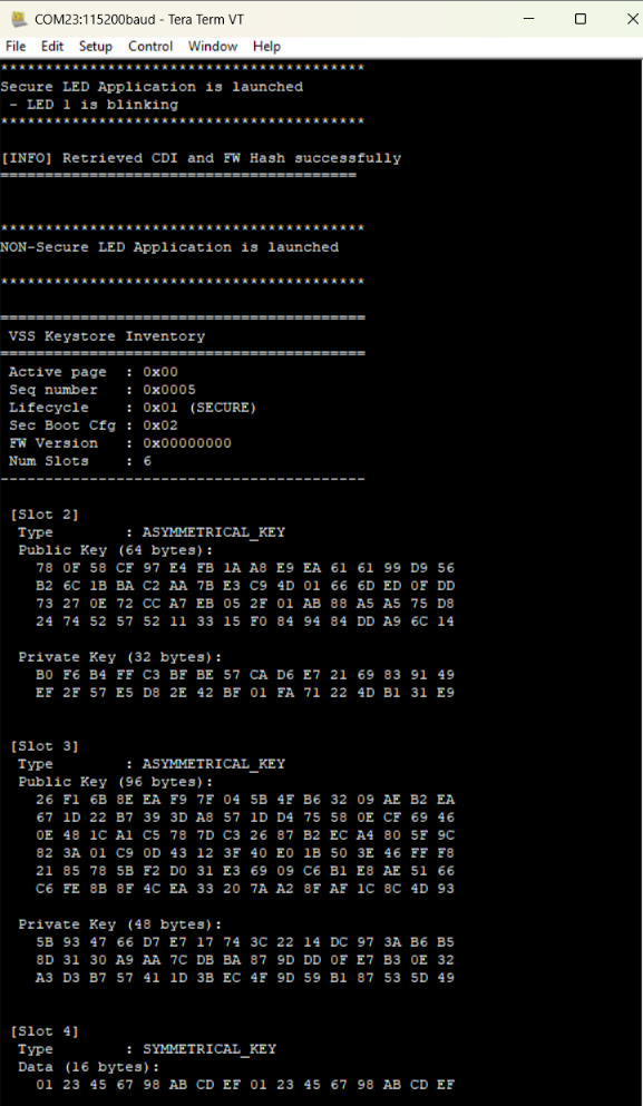
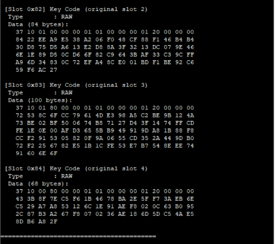
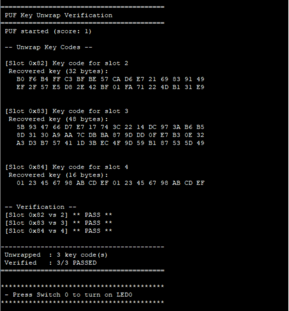
Expected Serial Console Output
Terminal settings: 115200 baud, 8-N-1, no flow control.
The output differs between the DICE and no-DICE variants only in the status line after the secure banner. The example below shows the DICE variant. For the no-DICE variant, the line [INFO] Retrieved CDI and FW Hash successfully is replaced by [INFO] DICE is disabled.
After this output, the system enters Idle mode:
- LED1 continues blinking (SysTick ISR in Secure world)
- LED0 responds to physical button press (SW0)
- No further serial output unless an error occurs
Error Conditions
| Symptom | Cause | Console Output |
|---|---|---|
| No output at all | Secure boot failed, image not authenticated | (nothing - ROM Boot halts) |
| Only "Secure LED App" banner | NS image invalid or not present | Stops after banner |
| Slot shows "(none)" | Slot has no data in unencrypted segment | Check VSS XML config |
| PUF Unwrap FAIL (0xD3) | Wrong PUF AC loaded or device mismatch | FAIL: PUF Unwrap failed |
| Verification FAIL | Key material was corrupted in Flash | [Slot X vs Y] FAIL |
| PUF AC not found | Step 1a was not executed | PUF start fails |