
2.2.1.1 Data Frames Over UART
Note: The framing strategy discussed here is only for
UART. For CAN FD, framing follows the standard. Concepts such as IDs and signal channel
offsets apply equally to every frame regardless of the underlying physical layer.
Figure 1 shows the structure and composition of a UART data frame, detailing the arrangement and function of each byte and field within the frame.
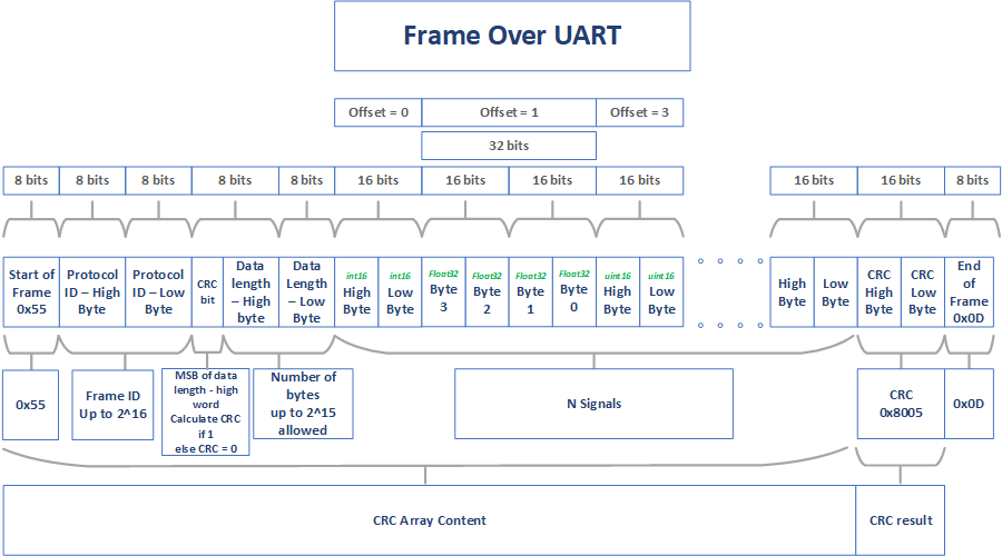
Table 1 lists a detailed description of each field present in the UART frame, explaining their roles and specific values.
| Name | Description |
|---|---|
| Start of Frame | Marks the start of frame. Always 0x55 |
| Protocol ID | Allowed up to 0xFFFF (65355) |
| CRC Bit | The Most Significant bit of the data length high byte indicates whether a CRC is included. If it is high, then the CRC word must be appended to the message before the end of frame. If it is low, then CRC word must be zero. |
| Data Length | Total number of bytes that are being sent in this frame. The maximum number of bytes that can be sent is 215 (that is, 0x7FFF (32767)). |
| Signal Channel Data | Each signal channel consists of bytes arranged in big-endian format. |
| CRC | CRC is calculated from the generator polynomial 0x8005. |
| End of Frame | Always 0x0D |