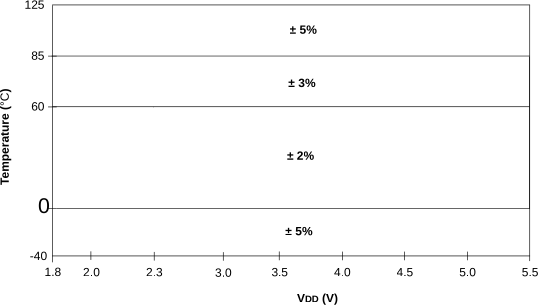
50.11 Internal Oscillator Parameters(1)
| Standard Operating Conditions (unless otherwise stated) | |||||||
|---|---|---|---|---|---|---|---|
| Param No. | Sym. | Characteristic | Min. | Typ. † | Max. | Units | Conditions |
| OS50 | FHFOSC | Precision Calibrated HFINTOSC Frequency | — |
4 8 12 16 32 48 64 | — | MHz | (Note 2) |
| OS51 | FHFOSCLP | Low-Power Optimized HFINTOSC Frequency | 0.9 | 1 | 1.1 | MHz | -40°C ≤ TA ≤ +85°C |
| OS51A | 1.8 | 2 | 2.2 | MHz | -40°C ≤ TA ≤ +85°C | ||
| OS51B | 0.88 | 1 | 1.12 | MHz | +85°C ≤ TA ≤ +125°C | ||
| OS51C | 1.76 | 2 | 2.24 | MHz | +85C ≤ TA ≤ +125°C | ||
| OS52* | FMFOSC | Internal Calibrated MFINTOSC Frequency | — | 500 | — | kHz | |
| OS53* | FLFOSC | Internal LFINTOSC Frequency |
— | 31 |
— | kHz | |
| OS54* | THFOSCST | HFINTOSC Wake-up from Sleep Start-up Time | — | 19 | — | μs |
VREGPM = System Clock at 4 MHz |
| OS54A* | — | 30 | — | μs |
VREGPM = System Clock at 4 MHz | ||
| OS54B* | — | 115 | — | μs |
VREGPM = System Clock at 4 MHz | ||
| OS54C* | — | 120 | — | μs |
VREGPM = System Clock at 4 MHz | ||
| OS56* | TLFOSCST | LFINTOSC Wake-up from Sleep Start-up Time | — | 900 | — | μs |
VREGPM = |
|
* These parameters are characterized but not tested. † Data in “Typ” column is at 3.0V, 25°C unless otherwise stated. These parameters are for design guidance only and are not tested. Note:
| |||||||