2.2.1.2.1 Steps to Utilize Model-Based Design in Harmony QSpin
Follow the following steps to utilize Model-Based Design in Harmony QSpin.
Presently, this support is available only for PIC32MK, SAME70, SAME54, and SAMRH707 device families.
1. Install X2C Library
Refer to the installation instructions to install the X2C library (if not already installed).
2. Configure Harmony QSpin GUI
Create MCC Harmony Project and configure the motor, peripherals, and hardware as mentioned in the Getting Started section.
3. Navigate to the Motor Control and Diagnosis Block
Open Harmony QSpin GUI and navigate to the Motor Control and Diagnosis block.
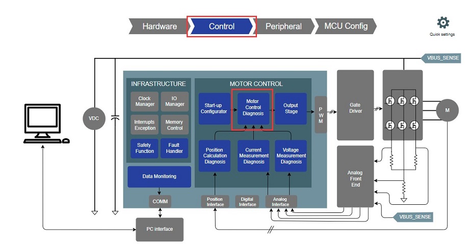
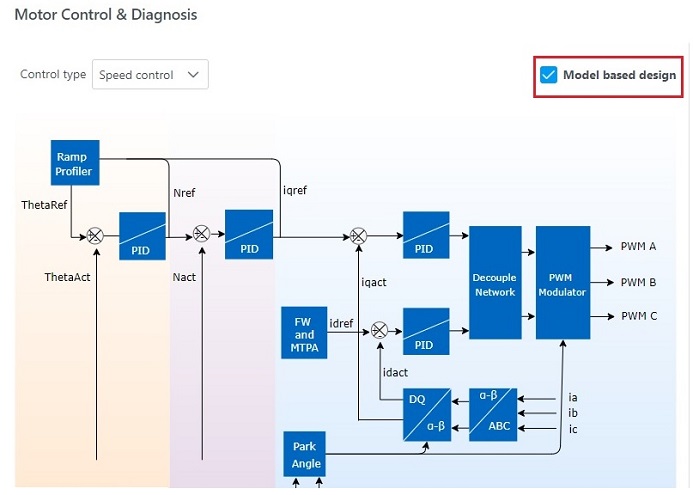
4. Enable Model-Based Development Option
Within the Motor Control and Diagnosis block, check the "Model Based Development" option. This setting instructs QSpin to generate wrapper files instead of code for motor control.
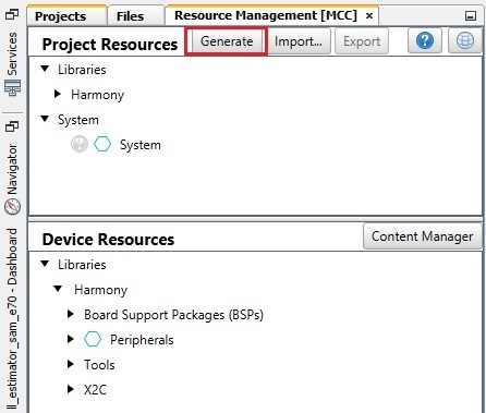
5. Generate C Code from MCC
Use the Motor Control Center (MCC) to generate the C code necessary for your project.
6. Launch Scilab for X2C-based Model-Based Design
There are two ways to launch Scilab for X2C-based model-based design:
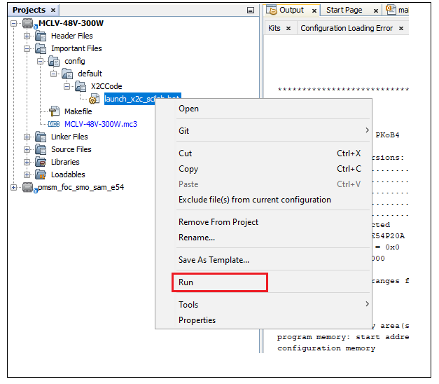
Using a Batch File:
- Navigate to the project explorer and locate the following path:
Important Files -> config -> default -> X2CCode. - Find the file named
launch_x2c_scilab.bat. - Right-click on
launch_x2c_scilab.batand select "Run" to launch Scilab automatically.
Manual Steps:
- Open Windows Explorer and manually launch Scilab.
- Navigate to the X2C code directory within your project, ensuring that
X2CCodeis set as the root folder. - In this directory, locate the
initProject.scefile and execute it to initialize the project in Scilab.
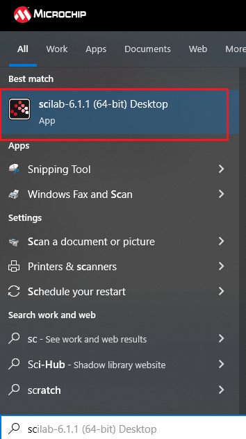
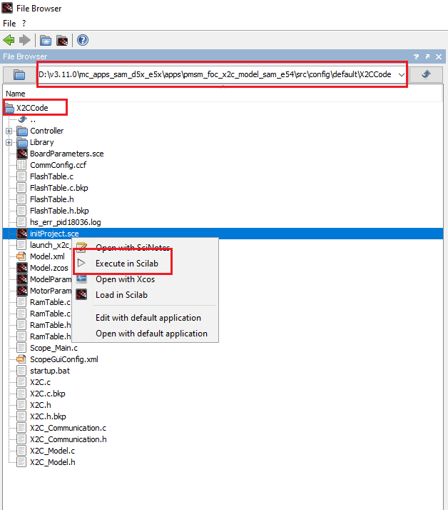
7. Model Creation in X2C
Use X2C to create your model. For detailed instructions and guidance on model creation, transformation, and other relevant processes, refer to the following resources:
- X2C - Model based development and Code generation
- Scilab® and X2C Open-Source Tools for Motor Control Development
- Harmony X2C Model
You can use sample X2C models from motor_control->algorithms->pmsm_foc->config->x2c-models to start your model based design.
8. Transform and Generate Code
- Click on "transform model and push to communicator".
- Click on "Start Communicator".
- Wait till you see "Model Set" in the log.
- Click on "Create Code" button.
- Transform your model in X2C and generate code as per your project requirements.
Your model name and files may differ from those shown in the figure, depending on your configuration, model, and version.
9. Update "readInports" and "writeOutports" Function Calls in MPLABX Project
Open mc_field_oriented_control.h from source->config->default->QSpin->Field_Oriented_Control.
Update readInports() and writeOutports() as shown in the provided code snippet.
Input Ports:
                    static inline void mcFoc_InputPortsRead( void  )
                    {
                    /** Please note that the ports may vary depending on your specific model.
                    Please adjust as needed. */
                    #if ( X2CMODEL_TYPE == FLOATING_POINT_F32_MODEL )
                    x2cModel.inports.bI_a = (float32_t)mcCurI_ModuleData_gds.dOutput.iABC.a;
                    x2cModel.inports.bI_b = (float32_t)mcCurI_ModuleData_gds.dOutput.iABC.b;
                    x2cModel.inports.bV_POT = mcHalI_Potentiometer_gdu16 - 2048;
                    x2cModel.inports.bV_DCLINK = (float32_t)mcVolI_ModuleData_gds.dOutput.uBus;
                    #endif

                    #if ( X2CMODEL_TYPE == FIXED_POINT_Q15_MODEL )
                    /** Scale phase currents
                    * Scaling:
                    *         Maximum measurable current -> 32767 units,
                    *         Conversion Factor = 32767./ Maximum measurable current
                    *
                    *         For a MCLV-48V-300W board, maximum measurable current is 22 Amperes
                    *         Therefore, conversion factor ~ 1,489.409
                    */
                    x2cModel.inports.bI_a = -(int16_t)((float32_t)mcCurI_ModuleData_gds.dOutput.iABC.a * (float32_t)1489.409);
                    x2cModel.inports.bI_b = -(int16_t)((float32_t)mcCurI_ModuleData_gds.dOutput.iABC.b * (float32_t)1489.409);

                    /**
                    Potentiometer scaling: [ 0 - 4095 ] -> [ -32768, 32767 ]
                    */
                    x2cModel.inports.bV_POT = (int16_t)( mcHalI_Potentiometer_gdu16  - 2048 )<< 3U;

                    /** Scale DC link voltage
                    * Scaling:
                    *         Maximum measurable voltage -> 32767 units,
                    *         Conversion Factor = 32767/ Maximum measurable voltage
                    *
                    *         For a MCLV-48V-300W board, maximum measurable voltage is 72.9 Volts
                    *         Therefore, conversion factor ~ 449.478
                    */
                    x2cModel.inports.bV_DCLINK = (int16_t)((float32_t)mcVolI_ModuleData_gds.dOutput.uBus * (float32_t)449.478);
                    #endif
                    }
Output Ports:
                    static inline void mcFoc_OutputPortsWrite( void  )
                    {
                    /** Please note that the ports may vary depending on your specific model.
                    Please adjust as needed. */
                    #if ( X2CMODEL_TYPE == FLOATING_POINT_F32_MODEL )
                    float32_t dutyCycleFactor;
                    int16_t   periodCount;
                    int16_t   halfPeriodCount;

                    /* Get the period count from mcHalI_PwmPeriodGet() */
                    periodCount = mcHalI_PwmPeriodGet();

                    /* Calculate half of the period count */
                    halfPeriodCount = periodCount >> 1U;

                    /* Calculate the duty cycle factor */
                    dutyCycleFactor = (float)periodCount / mcVolI_ModuleData_gds.dOutput.uBus;

                    /* Update PWM duty cycles for three channels */
                    mcPwmI_Duty_gau16[0] = periodCount - (halfPeriodCount + *x2cModel.outports.bPWM1 * dutyCycleFactor);
                    mcPwmI_Duty_gau16[1] = periodCount - (halfPeriodCount + *x2cModel.outports.bPWM2 * dutyCycleFactor);
                    mcPwmI_Duty_gau16[2] = periodCount - (halfPeriodCount + *x2cModel.outports.bPWM3 * dutyCycleFactor);
                    #endif

                    #if ( X2CMODEL_TYPE == FIXED_POINT_Q15_MODEL )
                    uint16_t duty[3U];
                    int16_t   periodCount;

                    /* Get the period count from mcHalI_PwmPeriodGet() */
                    periodCount = mcHalI_PwmPeriodGet();


                    duty[0u] = (uint16_t)(((INT16_MAX - *x2cModel.outports.bPWM1) * periodCount)>>16);
                    duty[1u] = (uint16_t)(((INT16_MAX - *x2cModel.outports.bPWM2) * periodCount)>>16);
                    duty[2u] = (uint16_t)(((INT16_MAX - *x2cModel.outports.bPWM3) * periodCount)>>16);

                    mcHalI_InverterPwmSet(duty);
                    #endif
                    }
10. Make and Program Device Project
Make and program the device project.
11. Verify X2C Communicator Communication
- Click on "Start Communicator" (if not already open).
- Setup Serial Port.
- Click on "Connect to Target".
Your model name and files may differ from those shown in the figure, depending on your configuration, model, and version.
12. Motor Operation, Variable Monitoring, and Tuning
Run the motor, monitor variables, and fine-tune your system parameters as needed for optimal performance.
