5.3 Configuring MIPI DSI
Module selection: Add the MIPI DSI driver to the project graph and link it to the SAMA7D65 DSI controller.
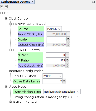
Parameters:
- Lane count: Use two data lanes for High-Speed (HS) mode to maximize bandwidth
- Transmission type: Non-burst with sync pulses
- Clock configuration: Set the DSI PLL to generate 1 GHz (lane bit rate)
Lane bit rate calculation:
Calculate the actual lane bit rate and the total DSI bandwidth required for the display using:
- 2 MIPI DSI lanes
- LCD pixel clock: 83.33 MHz
- Resolution: 720 × 1280
- 24-bit RGB (8 bits per color channel)
Step 1: Calculate the total data rate
The total pixel rate is:
Since each pixel is 24 bits (3 bytes) for RGB, the required raw data rate is:
Step 2: Calculate per lane bit rate
Since the display operates with 2 lanes, the total data rate is split evenly:
This value is configured in the DSI driver module present in the project graph in MPLAB Harmony.