
5.6 Pin Configuration
In MCC, use the Pin Manager or Pin Configuration tool to view the microcontroller’s pins graphically. In Harmony, use the Pin Configuration tab within the Configurator:
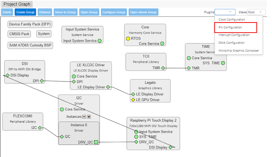
- Assign peripheral functions to specific pins based on the project graph.
- Configure pin settings such as input/output, pull-up/pull-down resistors or Analog/Digital mode.
- For the MIPI DSI display, configure the pins listed in the following table to enable I2C and DSI communication. The Pin Manager interface in MCC allows visual assignment of pins to peripherals. Map the signals as required, based on the SAMA7D65-Curiosity board and the assignments shown in the following table.
|
PIO |
Signal Name |
Signal Description |
|---|---|---|
|
PB18 |
MIPI_ENABLE_PB18 |
Display enable signal |
|
PB16 |
MIPI_IRQ_PB16 |
Display touchscreen interrupt line |
|
PB14 |
MIPI_PWM_PB14 |
Display PWM signal |
|
PC6 |
MIPI_TWCK_PC6 |
Display TWI clock signal |
|
PC7 |
MIPI_TWD_PC7 |
Display TWI data signal |
The SAMA7D65 supports MIPI DSI, which requires data lanes and a clock lane. The pin assignments for the DSI data and clock signals are typically fixed and handled by the DSI controller configuration in MCC, so they may not appear in the Pin Manager. However, control signals related to the display need to be assigned.
- Display and touch interface (I2C): the Raspberry Pi Touch Display 2 uses I2C for display and touch communication, requiring SDA (data) and SCL (clock) lines. An interrupt line may also be needed for touch events.
- LED indicators: if the board uses LEDs for status (for example, green/red LEDs), these can be configured as shown in Table 5-3.
The SAMA7D65-Curiosity Kit user guide (see References) shows the pins needed for the MIPI DSI display connection. Table 5-3 shows pin configurations in MPLAB Harmony.
| Pin ID | Custom Name | Function | Direction | Latch | Open Drain | PIO Interrupt | Pull Up | Pull Down |
|---|---|---|---|---|---|---|---|---|
| PB14 | MIPI_LCD_PWM | GPIO | Out | High | – | Disabled | – | – |
| PB15 | LED_GREEN | LED_AH | Out | Low | – | Disabled | – | – |
| PB16 | MIPI_IRQ | GPIO | In | N/A | – | Disabled | – | – |
| PB17 | LED_RED | LED_AH | Out | Low | – | Disabled | – | – |
| PB18 | MIPI_LCD_EN | GPIO | Out | High | – | Disabled | – | – |
| PC6 | MIPI_LCD_SCL | FLEXCOM_IO1 | N/A | N/A | – | Disabled | – | – |
| PC7 | MIPI_LCD_SDA | FLEXCOM_IO0 | N/A | N/A | – | Disabled | – | – |
| PC10 | USER_BUTTON | SWITCH_AL | In | Low | – | Disabled | X | – |
The above pins are configured using the Pin Manager settings in MCC, where essential pins are assigned for interfacing the SAMA7D65 with the Raspberry Pi Touch Display 2. This includes the configuration of MIPI DSI lanes, I2C lines for touch communication, and GPIOs for functions like reset, power enable and backlight control.