3.5.6 CLC2
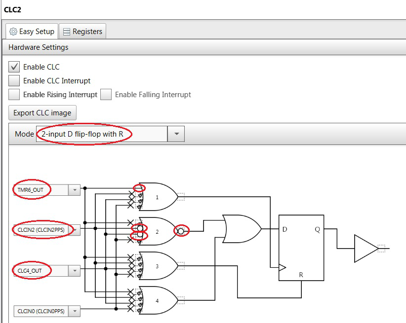
Configure CLC2 as shown in Figure 3-7. Select 2-input D flip-flop with R in the Mode field. Select TMR6_OUT as the clock to the D Flip-Flop register. Select CLC4_OUT (the output signal of CLC4) and logical AND-it with the default CLCIN2 (the input signal of CLC4) as an input signal to the CLC2. Connect the TMR6_OUT signal to the CLC logic gate 1 as highlighted in the red circle shown in Figure 3-7. Connect CLC4_OUT and CLCIN2 to the CLC logic gates 2 and invert both the input and output signals of the CLC logic gates 2 as highlighted in the red circles.