3.5.7 PINS
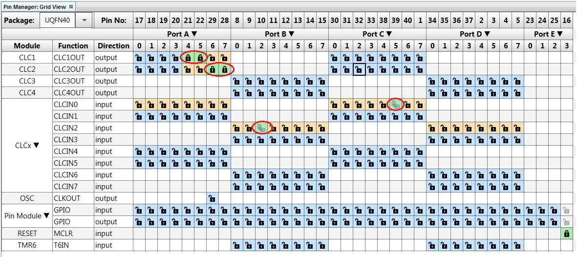
Click Pin Manager: Grid View to configure the input/output pins. Click RC5 and RB2 as input pins of CLCIN0 and CLCIN2 respectively, as highlighted in the red circles in Figure 3-8. Configure CLC1 output to pins RA4 and RA5 as highlighted in the red circle. Configure CLC2 output to pins RA6 and RA7 as highlighted in the red circle. Pins RA4, RD5, RA6, and RA7 are connected to the HPC board LEDs D2, D3, D4, and D5 respectively. RB2 will be manually connected to the external rotary button, while RC5 is already connected to the onboard button S2. The connection between the pins and the CLCs has been illustrated in Figure 2-1. The CLC1 output has been used to light the LEDs D2 and D3. The CLC2 output has been used to light the LEDs D4 and D5.

