
9.3 Program Frame Waveform
When performing Program, Verify or Authenticate actions, the data is clocked into the device starts at the beginning of the datastream block as shown in the following figure. This data is different depending on the device and the design, but in all cases, the data is clocked in 16 bytes at a time.
The following scope plots show how the first data frame is clocked.
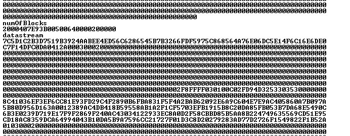
In this example, the following data is clocked.
| Bytes | |||||||||||||||
|---|---|---|---|---|---|---|---|---|---|---|---|---|---|---|---|
|
0 |
1 |
2 |
3 |
4 |
5 |
6 |
7 |
8 |
9 |
10 |
11 |
12 |
13 |
14 |
15 |
| 7C | 5D | 1C | 2B | 3D | 75 | 19 | B3 | 92 | 4A | AB | EE | 4E | D5 | 6C | 62 |
Mode 3 of the SPI mode is used and the data is clocked byte 0 MSB first. Note the following:
- Before performing any data shift, the target device SPI buffer status is checked by shifting 0xff. This is the only instruction that is 8 bit long, and the data is read out at the same time as it is shifted in. The result of the first shift is ignored.
- When shifting data, into the device, the first byte is the command followed by 16 bytes of data. 16 bytes of zero value must be shifted for commands that do not require data.
- Shifting data out from the device is a two steps operation. The command is clocked into the device first and then the data is clocked out using a read command of 0x5.
- All operations except for SPI
hardware status check are made of one byte of command followed by 16 bytes of data.
Chip Select (CS) line must be driven low before clocking the command and should
remain low until the last bit of data is shifted in. Then, it must be driven high to
execute the loaded instruction.Note: 1, 2, and 3 are taken care of by the programming algorithm.
- Checking hardware status.
Figure 9-79. Hardware Status Check 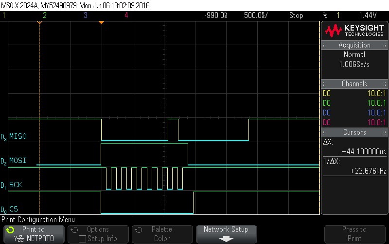
- Checking hardware status.
Figure 9-80. Hardware Status Check 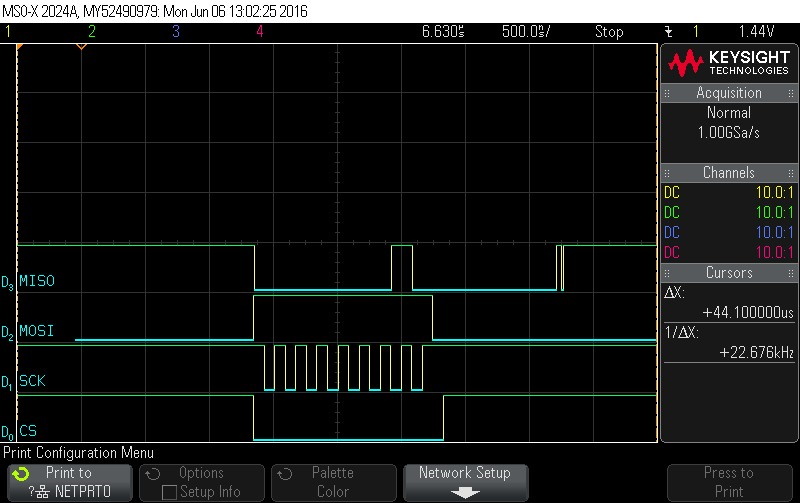
- Shift in the first frame. Command =
0x1. Data to follow. Note CS signal.
Figure 9-81. Shift in the First Frame. Command = 0x1. Data to Follow. Note CS Signal 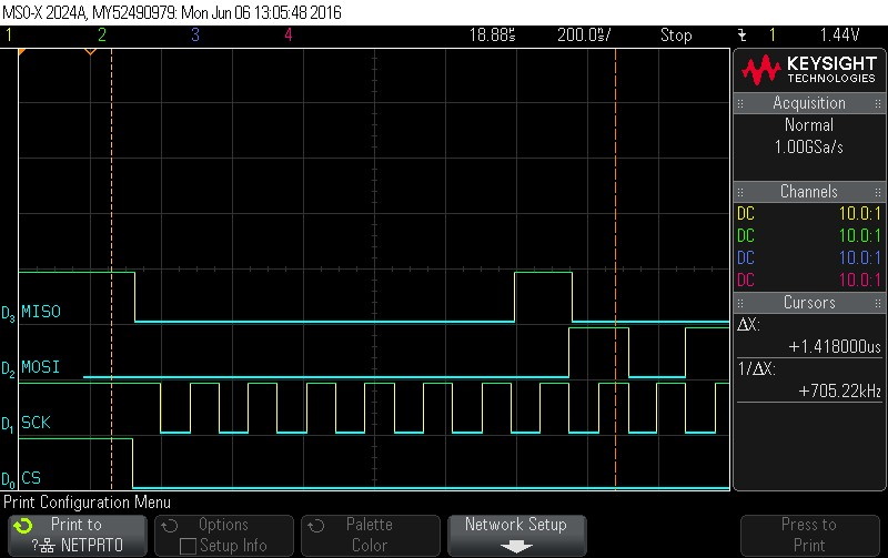
- Data Byte 0 = 0x7C
Figure 9-82. Data Byte 0 = 0x7C 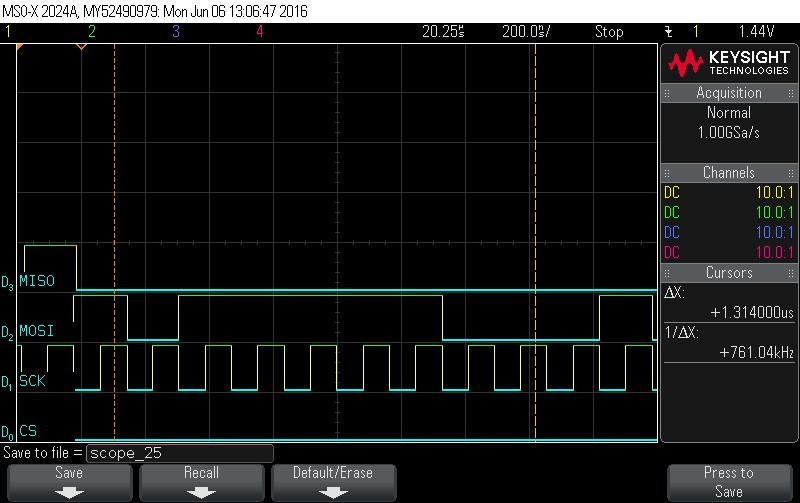
- Data Byte 1 = 0x5D
Figure 9-83. Data Byte 1 = 0x5D 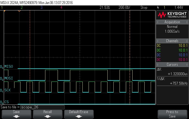
- Data Byte 2 = 0x1C
Figure 9-84. Data Byte 2 = 0x1C 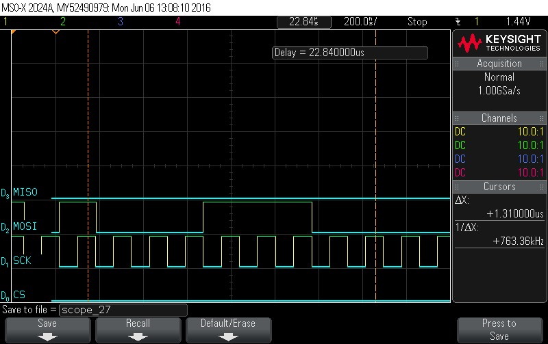
- Data Byte 3 = 0x2B
Figure 9-85. Data Byte 3 = 0x2B 
- Data Byte 4 = 0x3D
Figure 9-86. Data Byte 4 = 0x3D 
- Data Byte 5 = 0x75
Figure 9-87. Data Byte 5 = 0x75 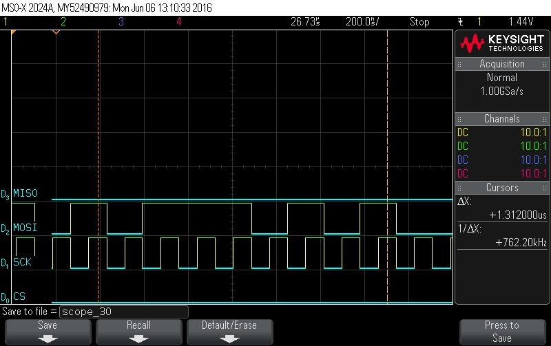
- Data Byte 6 = 0x19
Figure 9-88. Data Byte 6 = 0x19 
- Data Byte 7 = 0xB3
Figure 9-89. Data Byte 7 = 0xB3 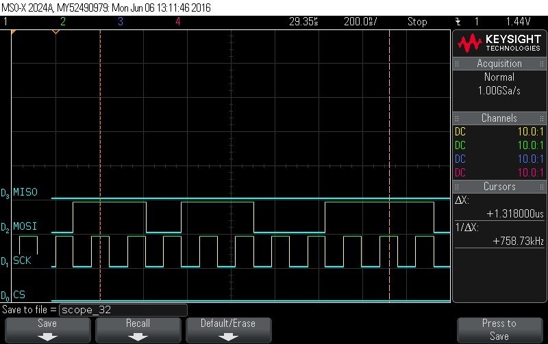
- Data Byte 8 = 0x92
Figure 9-90. Data Byte 8 = 0x92 
- Data Byte 9 = 0x4A
Figure 9-91. Data Byte 9 = 0x4A 
- Data Byte 10 = 0xAB
Figure 9-92. Data Byte 10 = 0xAB 
- Data Byte 11 = 0xEE
Figure 9-93. Data Byte 11 = 0xEE 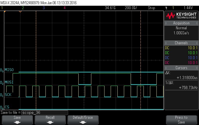
- Data Byte 12 = 0x4E
Figure 9-94. Data Byte 12 = 0x4E 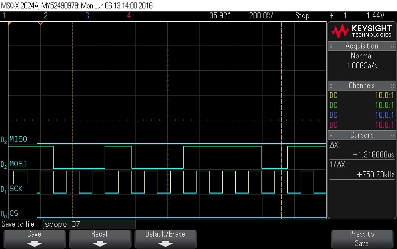
- Data Byte 13 = 0xD5
Figure 9-95. Data Byte 13 = 0xD5 
- Data Byte 14 = 0x6C
Figure 9-96. Data Byte 14 = 0x6C 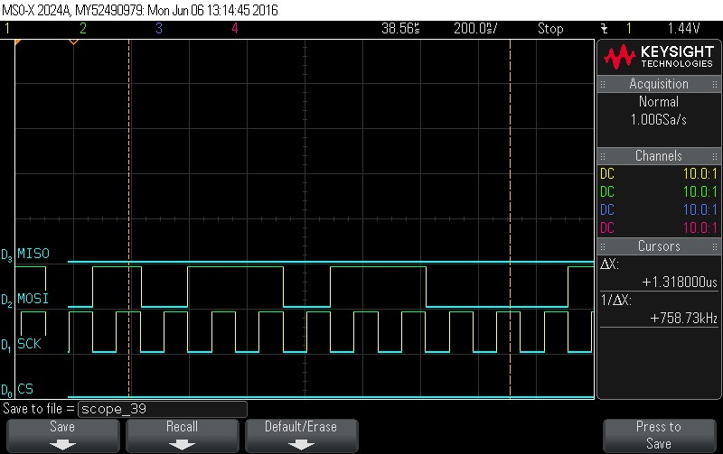
- At this point, the first frame of
data is clocked in. The next operation is to check the status.
Figure 9-97. Data Byte 15 = 0x62. Note CS signal 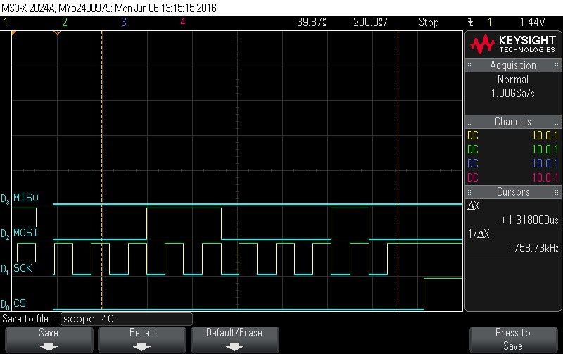
- Checking hardware status.
Figure 9-98. Hardware Status Check 
- Framing status command. Command =
0x4. Note CS signal.
Figure 9-99. Frame Status command. Command = 0x4. Note CS signal 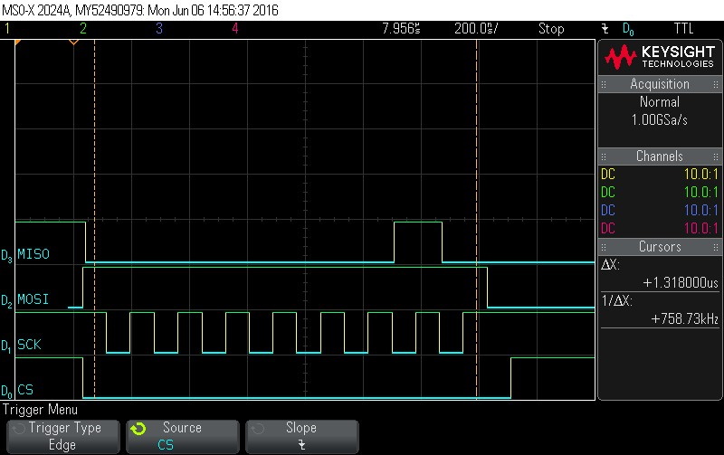
- Framing status command. Command =
0x4. Note CS signal.
Figure 9-100. Frame Status Command. Command = 0x4. Note CS signal 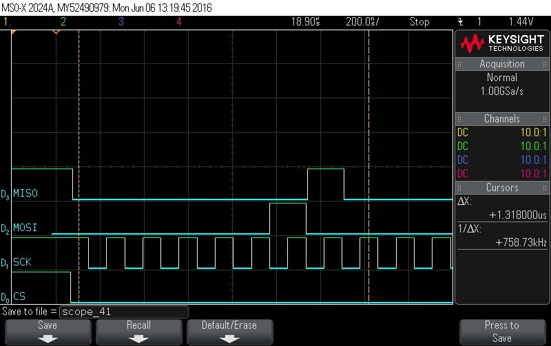
- Data Byte 0 = 0x0
Figure 9-101. Data Byte 0 = 0x0 
- Data Byte 1 = 0x0
Figure 9-102. Data Byte 1 = 0x0 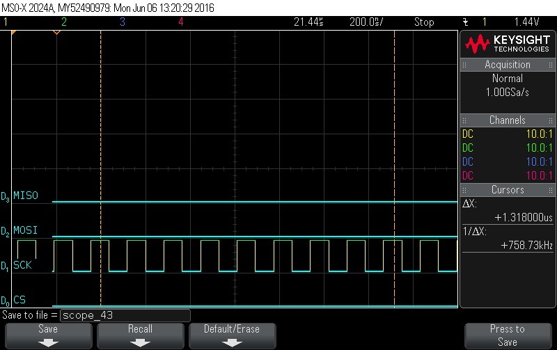
- Data Byte 2 = 0x0
Figure 9-103. Data Byte 2 = 0x0 
- Data Byte 3 = 0x0
Figure 9-104. Data Byte 3 = 0x0 
- Data Byte 4 = 0x0
Figure 9-105. Data Byte 4 = 0x0 
- Data Byte 5 = 0x0
Figure 9-106. Data Byte 5 = 0x0 
- Data Byte 6 = 0x0
Figure 9-107. Data Byte 6 = 0x0 
- Data Byte 7 = 0x0
Figure 9-108. Data Byte 7 = 0x0 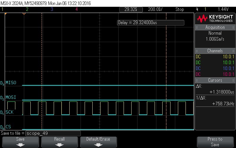
- Data Byte 8 = 0x0
Figure 9-109. Data Byte 8 = 0x0 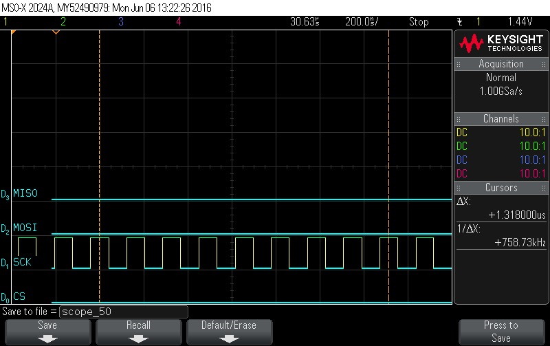
- Data Byte 9 = 0x0
Figure 9-110. Data Byte 9 = 0x0 
- Data Byte 10 = 0x0
Figure 9-111. Data Byte 10 = 0x0 
- Data Byte 11 = 0x0
Figure 9-112. Data Byte 11 = 0x0 
- Data Byte 12 = 0x0
Figure 9-113. Data Byte 12 = 0x0 
- Data Byte 13 = 0x0
Figure 9-114. Data Byte 13 = 0x0 
- Data Byte 14 = 0x0
Figure 9-115. Data Byte 14 = 0x0 
- Data Byte 15 = 0x0
Figure 9-116. Data Byte 15 = 0x0 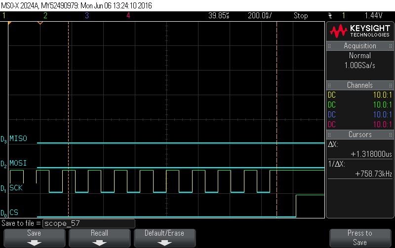
- Instruction is loaded. Issue read
instruction using 0x5 command.
Figure 9-117. Hardware Status Check 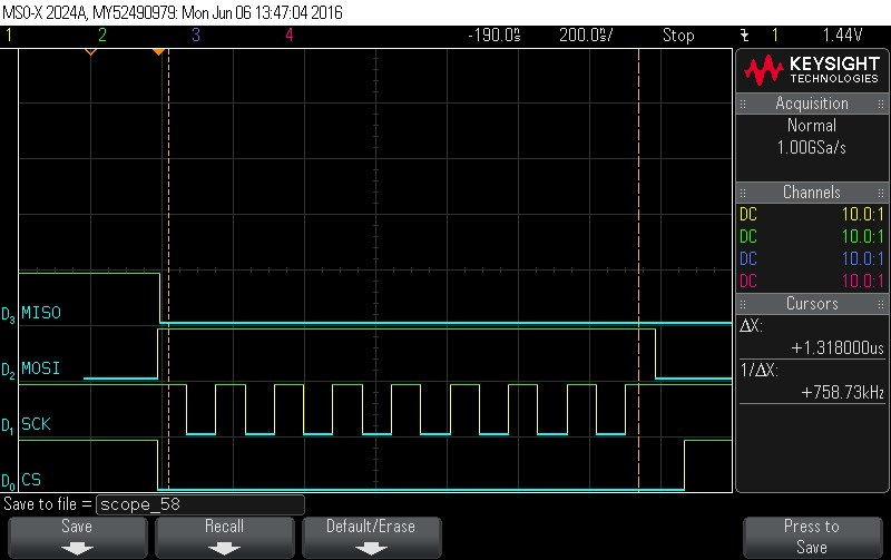
- Checking hardware status.
Figure 9-118. Hardware Status Check 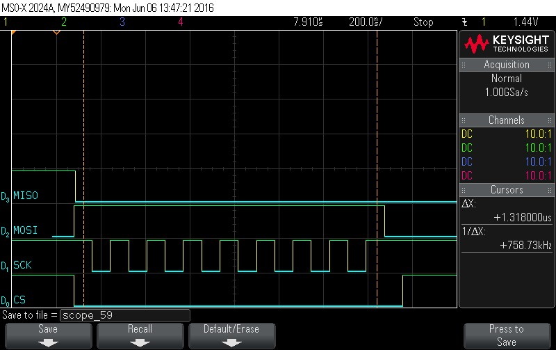
- Reading command. Command = 0x5. Note
CS signal.
Figure 9-119. Read Command. Command = 0x5. Note CS signal 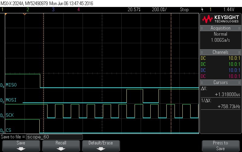
- Reading Data Byte 0.
Figure 9-120. Data Byte 0 read 
- Reading Data Byte 1.
Figure 9-121. Data Byte 1 read 
- Reading Data Byte 2.
Figure 9-122. Data Byte 2 read 
- Reading Data Byte 3.
Figure 9-123. Data Byte 3 Read 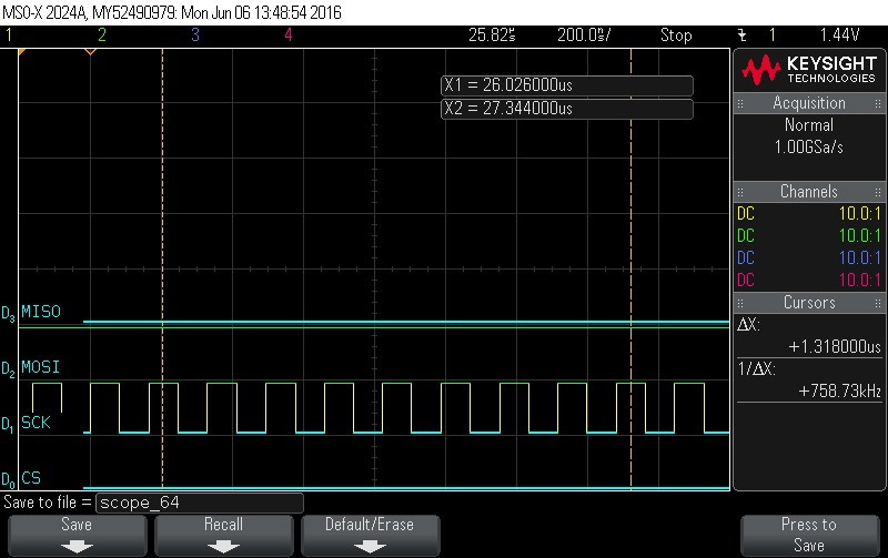
- Reading Data Byte 4.
Figure 9-124. Data Byte 4 Read 
- Reading Data Byte 5.
Figure 9-125. Data Byte 5 Read 
- Reading Data Byte 6.
Figure 9-126. Data Byte 6 Read 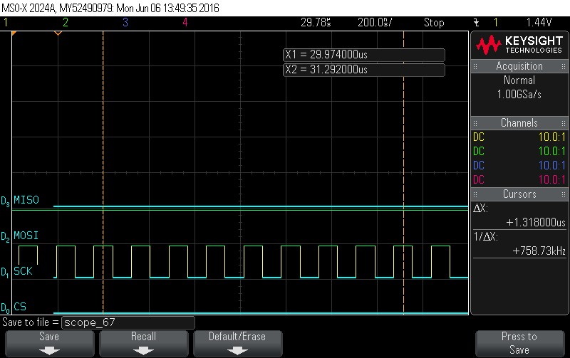
- Reading Data Byte 7.
Figure 9-127. Data Byte7 Read 
- Reading Data Byte 8.
Figure 9-128. Data Byte 8 Read 
- Reading Data Byte 9.
Figure 9-129. Data Byte 9 Read 
- Reading Data Byte 10.
Figure 9-130. Data Byte 10 Read 
- Reading Data Byte 11 read
Figure 9-131. Data Byte 11 Read 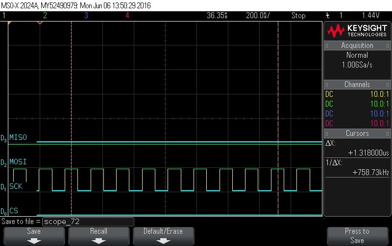
- Reading Data Byte 12.
Figure 9-132. Data Byte 12 Read 
- Reading Data Byte 13.
Figure 9-133. Reading Data Byte 13 
- Reading Data Byte 14.
Figure 9-134. Data Byte 14 Read 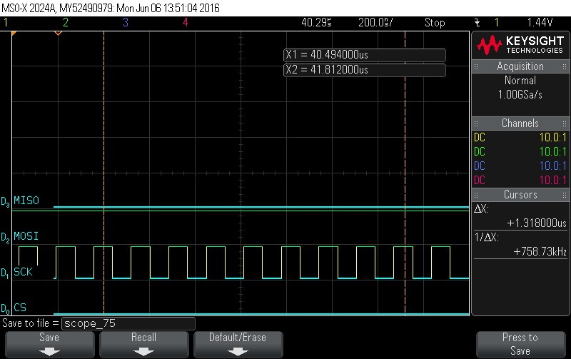
- Reading Data Byte 15.
Figure 9-135. Data Byte 15 Read 