3.5.1 ATWINC1500 and PIC32MX Pin Mapping
The following are the pin mapping details of the ATWINC15x0 with PIC32MX host.
| ATWINC1500 Pin | PIC32 Port Pin |
|---|---|
| Chip Enable | RF1 |
| Reset | RF0 |
| Interrupt | RE8 (INT1) |
| SPI Clock | RD10 (SCK1) |
| SPI Data IN | RD0 (SDO1) |
| SPI Data OUT | RC4 (SDI1) |
| SPI Slave Select | RD9 (SS1) |

- In the MHC, open the Wi-Fi module.
- Select WINC1500 for the Wi-Fi driver.
- Enter the pin mapping details based
on the ATWINC15x0 and PIC32MX hardware
design.
Figure 3-10. Pin Mapping 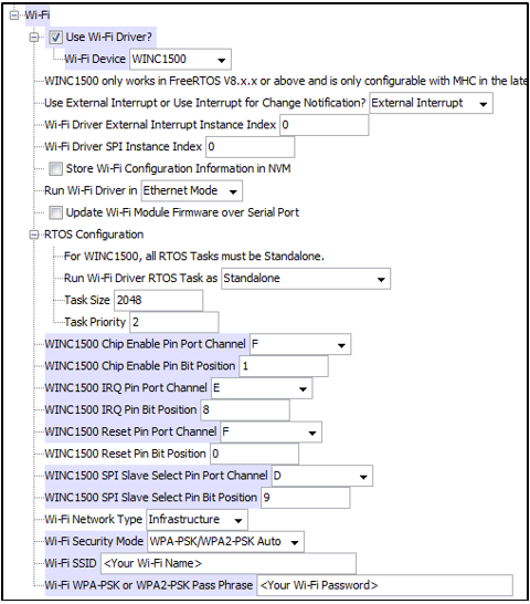
See the Pin Mapping section for the Explorer 16 Board and WINC15x0 pin mapping details.
The ATWINC15x0 uses the External Interrupt to Change notification. To use this, the user needs to configure the external interrupt service under System Services.
- Navigate to MHC System Services, and enable Use External Interrupts? to be used by the Wi-Fi driver.
- Under External Interrupt Instance 0, change the Module ID to INT_SOURCE_1 because the ATWINC1500 interrupt pin connects to INT1.
- Enable Generate ISR Code?.
- Set the Interrupt Priority to Level 3.
- Set the Interrupt Sub-priority to Level 1.
- Set the Polarity to EDGE_TRIGGER_FALLING.
Figure 3-11. External Interrupt Setup 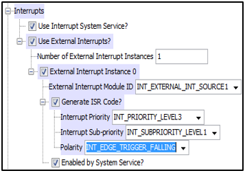
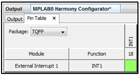
In the Pin Table table, assign pin 18 (RE8) to the External Interrupt 1 module, as shown ion the following image.