3.5 PICkit™ On-Board 4 (PKOB4) and Debugger/Programmer Selection (U300)
Features and Capabilities of PKOB4:
- Connects to a Computer Through High-Speed USB 2.0 (480 Mbits/s) Cable
- Programs the Device Using MPLAB® X IDE or MPLAB® IPE
- Supports Multiple Hardware and Software Breakpoints, Stopwatch and Source Code File Debugging
- Debugs the Application in Real Time
- Sets Breakpoints Based on the Internal Events
- Monitors the Internal File Registers
- Debugs at Full Speed
- Configures the Pin Drivers
- Field-Upgradeable Through an MPLAB X IDE Firmware Download
- Indicates Debugger Status Through On-Board LEDs, Demonstrating the Development Board’s Functionality and Features
The PKOB4 on the PIC32 BZ6 Curiosity Board is intended to support programming and debugging the target device (PIC32WM-BZ6204UE Module) through the debug USB Type-C® connector (J100) from the host PC. The PIC32 BZ6 Curiosity Board does not use the other PKOB4 features, such as data gateway and PKOB4 virtual COM port.
By default, the on-board debugger (PKOB4) is connected to the programming pins (SWDIO and SWDCLK) of the PIC32WM-BZ6204UE Module.
The voltage level translators are provided on signals between the PKOB4 and PIC32WM-BZ6204UE Module for supporting target voltage from 1.9–3.6V.
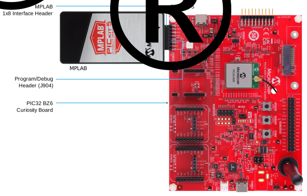
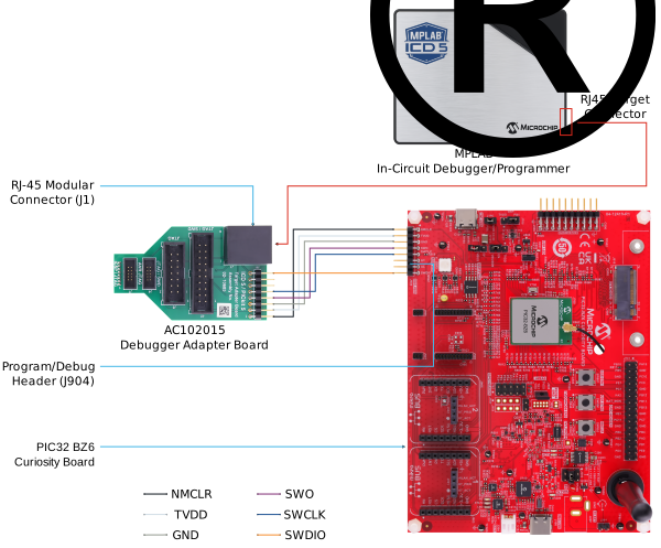
In addition, the PIC32 BZ6 Curiosity Board supports external debuggers, such as MPLAB® ICD5, MPLAB® PICkit™ 5 In-Circuit Debugger, and MPLAB® SNAP by connecting to the program/debug header (J904).
The program/debug header (J904) follows the standard MPLAB® PICkit™ 5 1x8 interface (see Figure 3-5). Connect the MPLAB ICD5 to the debug header using the debugger adapter board (AC102015) (see Figure 3-6). For more details, refer to the AC102015 product page.
| Pin Number of Debug Header | Pin Name | Description |
|---|---|---|
| 1 | NMCLR | PIC32WM BZ6204 Reset NMCLR pin |
| 2 | VDD_VIOREF | TVDD |
| 3 | GND | Ground |
| 4 | SWO | PB7, optional trace output |
| 5 | SWCLK | PB8, SWD programming clock |
| 6 | NC | No connection |
| 7 | NC | No connection |
| 8 | SWDIO | PB9, SWD programming data |
Note: PB9 is also shared between the user button 1 and mikroBUS™ 2 SPI Chip Select. | ||