
5.6 Decoupling Capacitors Selection
For optimal operation, VCC decoupling is crucial for all gate driver ICs. With poor decoupling, larger VCC transients will occur at the IC when switching, and for greater and longer VCC drop the IC can go into UVLO.
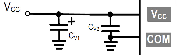
As shown in Figure 5-7, two decoupling capacitors are recommended, CV1 and CV2. CV1 can be a larger electrolytic, for example 47 μF, 50V, used to dampen low frequency drains on supply. CV1 does not need to be right next to the IC. CV2 is used to decouple faster edge changes to VCC, and should be a low ESR ceramic capacitor placed close to the VCC pin. This component provides stability when VCC is quickly pulled down with load from the IC. The typical value is 0.1 μF to 1 μF.
For applications with multiple gate driver ICs (for example, BLDC motor drive with three gate drivers, as shown in Figure 5-1), one larger electrolytic (CV1) can be used and the three ceramic capacitors (CV2, CV3, CV4) should be placed close to the VCC pin (see Layout section).