
3.4.5 PLC Coupling
The PL360MB evaluation board supports a set of PLC coupling boards, PLCOUPxxx, with the aim of easing the testing of different coupling reference designs while requiring only one PL360MB board. Furthermore, this functionality allows the same base board to cover several frequency bands by using the proper coupling board and firmware configuration. Table 3-20 summarizes the main features of the available PLCOUPxxx boards.
| Board Name | Description | Frequency Band (kHz) | Branch | Electrical Isolation | PRIME Channel | G3-PLC Band | Applicable Regulation |
|---|---|---|---|---|---|---|---|
| PLCOUP002 | G3 ARIB & PRIME ARIB (Channels 4 to 7) compliant | 206 – 417 | Double | Yes | 4, 5, 6, 7 | G3 ARIB | ARIB [STD-T84 Ver 1.0] |
| PLCOUP006 | G3 FCC & PRIME FCC (Channels 3 to 8) and KN60 compliant | 151 – 472 | Double | Yes | 3, 4, 5, 6, 7, 8 | G3 FCC | FCC [part 15 – 91905] |
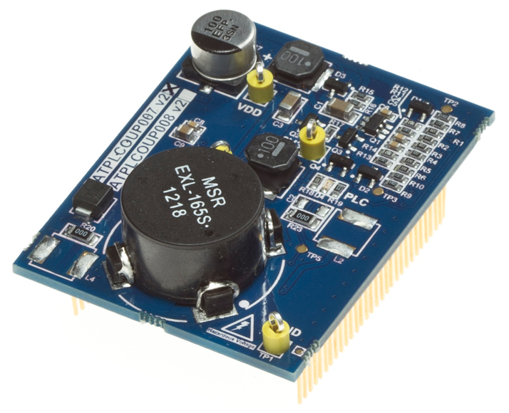
| PLCOUP007 | G3 CEN-A & PRIME CEN-A compliant | 35 – 91 | Single | Yes | 1 | G3 CEN-A | CEN-A [EN50065] |
| PLCOUP008 | Non-Isolated G3 CEN-A & PRIME CEN-A compliant | 35 – 91 | Single | No | 1 | G3 CEN-A | CEN-A [EN50065] |
| PLCOUP011 | G3 CEN-A, G3 FCC, PRIME CEN-A & PRIME FCC (Channels 3 to 8) compliant | 35 – 91 & 151 - 472 | Double | Yes | 1, 3, 4, 5, 6, 7, 8 | G3 CEN-A & G3 FCC | CEN-A [EN50065] |
| PLCOUP012 | Low cost with internal driver G3 CEN-B compliant | 95 - 125 | Single | Yes | 2 | G3 CEN-B | CEN-B [EN50065] |
| PLCOUP013 | Ultra low cost with internal driver and non-Isolated G3 CEN-B compliant | 95 - 125 | Single | No | 2 | G3 CEN-B | CEN-B [EN50065] |
| PLCOUP014 | G3 CEN-B compliant | 95 - 125 | Single | Yes | 2 | G3 CEN-B | CEN-B [EN50065] |
As shown in Figure 3-11, PL360MB has the possibility of disconnecting the PLC signal from the mains grid and connecting it to the BNC port, J11. This can be done by means of removing R12 and R13 and adding R88 and R89. This allows the possibility of using a dedicated communication channel for the PLC signal and eases the realization of certain PLC performance measurements.