
5.2 Sensor Configuration Register (CONFIG)
The MCP9808 has a 16-bit Configuration register (CONFIG) that allows the user to set various functions for a robust temperature monitoring system. Bits 10 through 0 are used to select the temperature alert output hysteresis, device shutdown or Low-Power mode, temperature boundary and critical temperature lock, and temperature Alert output enable/disable. In addition, Alert output condition (output set for TUPPER and TLOWER temperature boundary or TCRIT only), Alert output status and Alert output polarity and mode (Comparator Output or Interrupt Output mode) are user-configurable.
The temperature hysteresis bits 10 and 9 can be used to prevent output chatter when the ambient temperature gradually changes beyond the user-specified temperature boundary (see Temperature Hysteresis (THYST). The Continuous Conversion or Shutdown mode is selected using bit 8. In Shutdown mode, the band gap temperature sensor circuit stops converting temperature and the Ambient Temperature register (TA) holds the previous temperature data (see Shutdown Mode). Bits 7 and 6 are used to lock the user-specified boundaries TUPPER, TLOWER and TCRIT to prevent an accidental rewrite. The Lock bits are cleared by resetting the power. Bits 5 through 0 are used to configure the temperature Alert output pin. All functions are described in Table 5-3 (see Alert Output Configuration).
| U-0 | U-0 | U-0 | U-0 | U-0 | R/W-0 | R/W-0 | R/W-0 |
| — | — | — | — | — | THYST | SHDN | |
| bit 15 | bit 8 | ||||||
| R/W-0 | R/W-0 | R/W-0 | R-0 | R/W-0 | R/W-0 | R/W-0 | R/W-0 |
| Crit. Lock | Win. Lock | Int. Clear | Alert Stat. | Alert Cnt. | Alert Sel. | Alert Pol. | Alert Mod. |
| bit 7 | bit 0 | ||||||
| R = Readable bit | W = Writable bit | U = Unimplemented bit, read as ‘0’ | |||||
| -n = Value at POR | ‘1’ = Bit is set | ‘0’ = Bit is cleared | x = Bit is unknown | ||||
| 15-11 | Unimplemented: Read as ‘0’ | ||||||
| 10-9 | THYST: TUPPER and TLOWER Limit Hysteresis bits
(Refer to Alert Output Configuration.) This bit can not be altered when either of the Lock bits are set (bit 6 and bit 7). This bit can be programmed in Shutdown mode. | ||||||
| 8 | SHDN: Shutdown Mode bit
In shutdown, all power-consuming activities are disabled, though all registers can be written to or read. This bit cannot be set to ‘ | ||||||
| 7 | Crit. Lock: TCRIT Lock bit
When enabled, this bit remains set to ‘ This bit can be programmed in Shutdown mode. | ||||||
| 6 | Win. Lock: TUPPER and TLOWER Window Lock bit
When enabled, this bit remains set to ‘ This bit can be programmed in Shutdown mode. | ||||||
| 5 | Int. Clear: Interrupt Clear bit
This bit can not be set to ‘1’ in Shutdown mode, but it can be cleared after the device enters Shutdown mode. | ||||||
| 4 | Alert Stat.: Alert Output Status bit
This bit can not be set to ‘1’ or cleared to ‘0’ in Shutdown mode. However, if the Alert output is configured as Interrupt mode, and if the host controller clears to ‘ | ||||||
| 3 | Alert Cnt.: Alert Output Control bit
This bit can not be altered when either of the Lock bits are set (bit 6 and bit 7). This bit can be programmed in Shutdown mode, but the Alert output will not assert or deassert. | ||||||
| 2 | Alert Sel.: Alert Output Select bit
When the Alarm Window Lock bit is set, this bit cannot be altered until unlocked (bit 6). This bit can be programmed in Shutdown mode, but the Alert output will not assert or deassert. | ||||||
| 1 | Alert Pol.: Alert Output Polarity bit
This bit cannot be altered when either of the Lock bits are set (bit 6 and bit 7). This bit can be programmed in Shutdown mode, but the Alert output will not assert or deassert. | ||||||
| 0 | Alert Mod.: Alert Output Mode bit
This bit cannot be altered when either of the Lock bits are set (bit 6 and bit 7). This bit can be programmed in Shutdown mode, but the Alert output will not assert or deassert. | ||||||
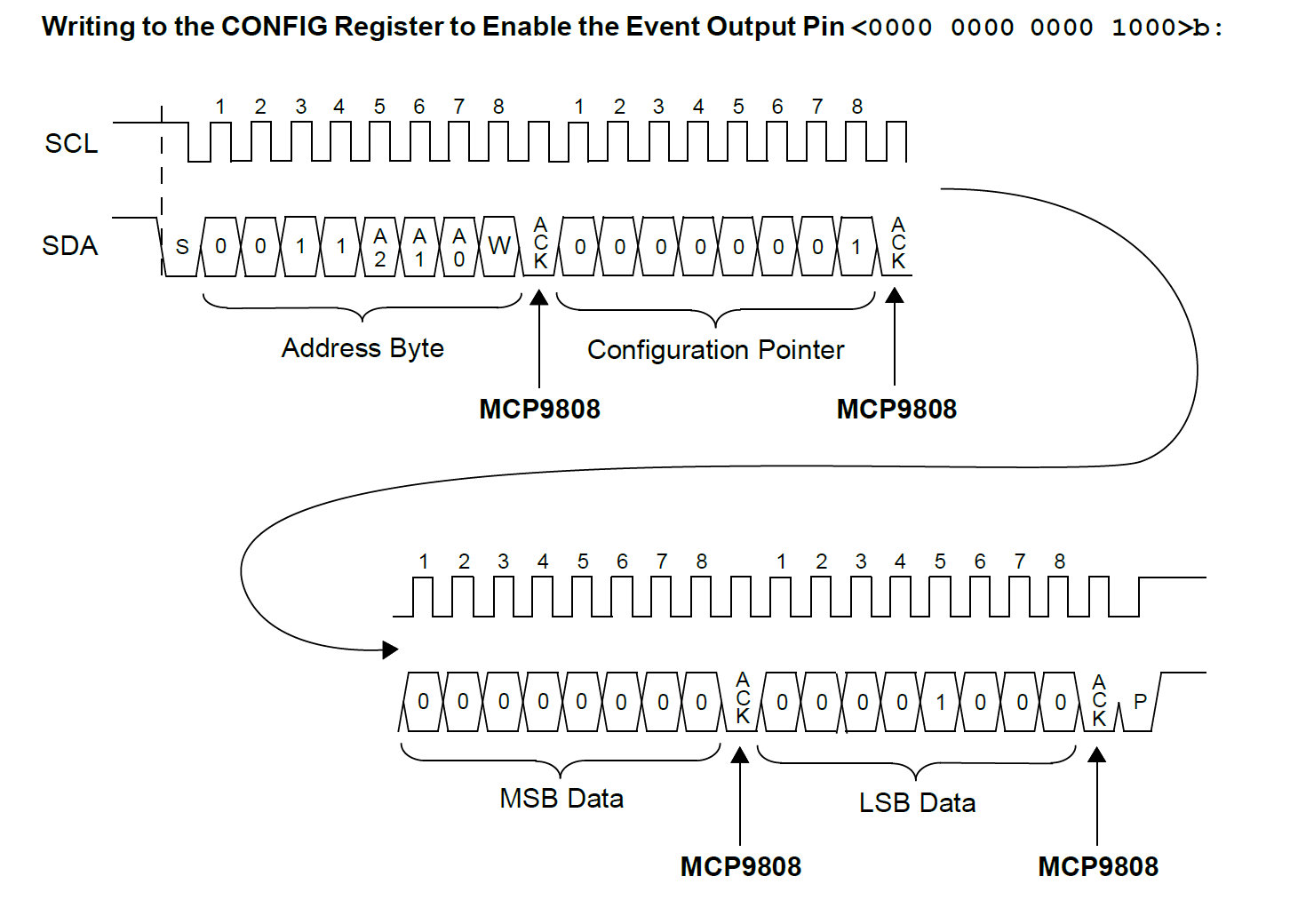
i2c_start(); // send START command
i2c_write(AddressByte & 0xFE); //WRITE Command (see Table 3-2)
//also, make sure bit 0 is cleared ‘0’
i2c_write(0x01); // Write CONFIG Register
i2c_write(0x00); // Write data
i2c_write(0x08); // Write data
i2c_stop(); // send STOP command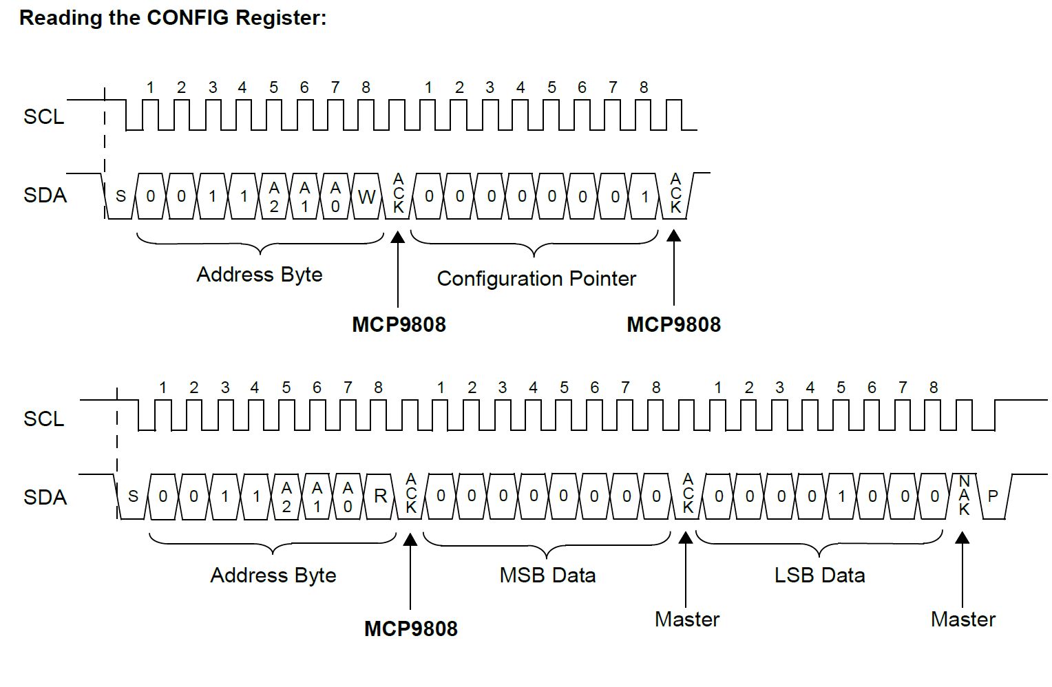
i2c_start(); // send START command
i2c_write(AddressByte & 0xFE); //WRITE Command (see Table 3-2)
//also, make sure bit 0 is cleared ‘0’
i2c_write(0x01); // Write CONFIG Register
i2c_start(); // send Repeat START command
i2c_write(AddressByte | 0x01); //READ Command
//also, make sure bit 0 is set ‘1’
UpperByte = i2c_read(ACK); // READ 8 bits
//and Send ACK bit
LowerByte = i2c_read(NAK); // READ 8 bits
//and Send NAK bit
i2c_stop(); // send STOP command