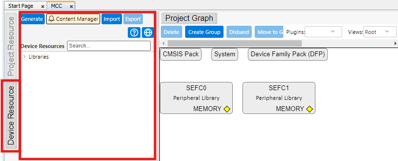
In MCC Project Graph window, expand
the Device Resource pane by clicking its button on the left of Project Graph.Figure 2-6. Device Resource
Pane
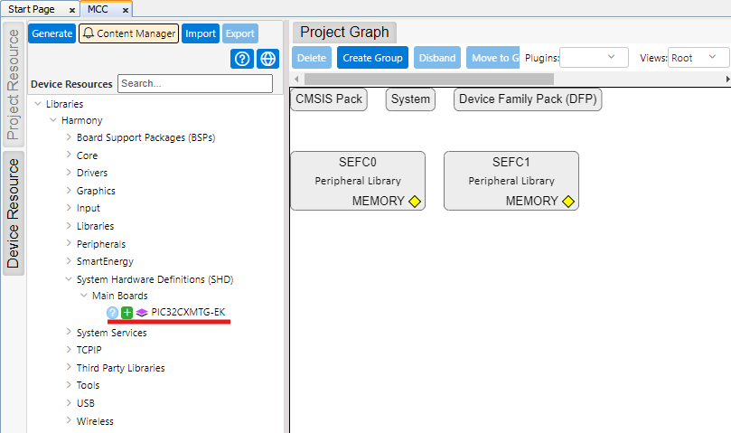
Look for PIC32CXMTG-EK component
under SHD category and add it using the Green Plus sign.Figure 2-7. Add PIC32CXMTG-EK
Component
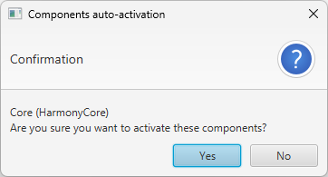
This automatically triggers the
activation of Core component. Click Yes to activate it.Figure 2-8. Core Component Auto
Activation
FreeRTOS component can also be
activated (it is offered), but in the case it is not needed, so click No when
prompted.
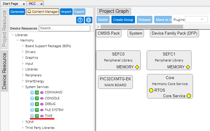
Time Component.
Navigate to System Services
and add TIME component by clicking the Green Plus sign.Figure 2-9. Add Time
Component
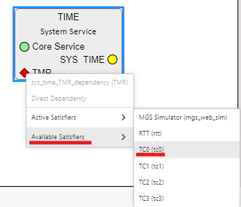
Right-click the TMR
dependency and select Available Satisfiers>TC0 (tc0).Figure 2-10. Select TC0 for
TMR
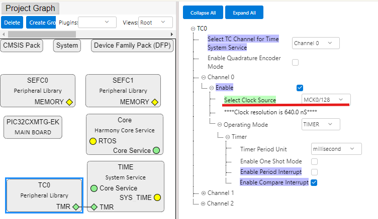
Modify Clock Source on TC0
component, as there is no need for accuracy in this project.Figure 2-11. Modify Clock
Source on TC0
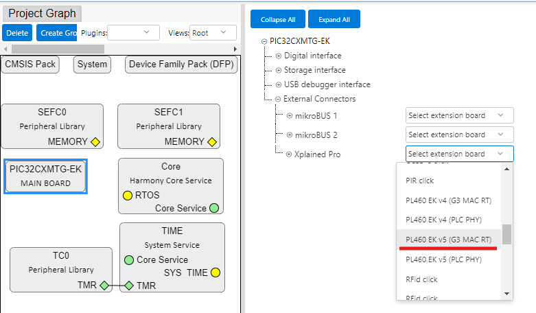
On PIC32CXMTG-EK Main Board
component, select PL460-EK v5 (G3 MAC RT) to be connected to Xplained Pro
Connector.Figure 2-12. Select PL460-EK v5 on
Xplained Pro Connector
This automatically adds, and configures the following components:
G3 MAC RT Driver
FLEXCOM5
PLC PVDD Monitor
ADC
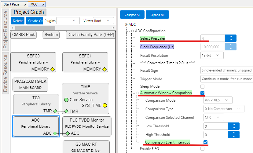
Most of these components are
auto-configured by PIC32CXMTG-EK component when components are auto-activated. Only
ADC has to be manually configured to set its prescaler and enable an interrupt, as
shown in the following figure.Figure 2-13. ADC Manual
Configuration
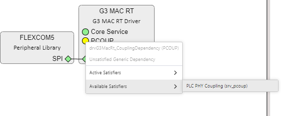
On G3 MAC RT component, right-click
the PCOUP Dependency and select PLC PHY Coupling from Available Satisfiers.Figure 2-14. Add PLC PHY
Coupling
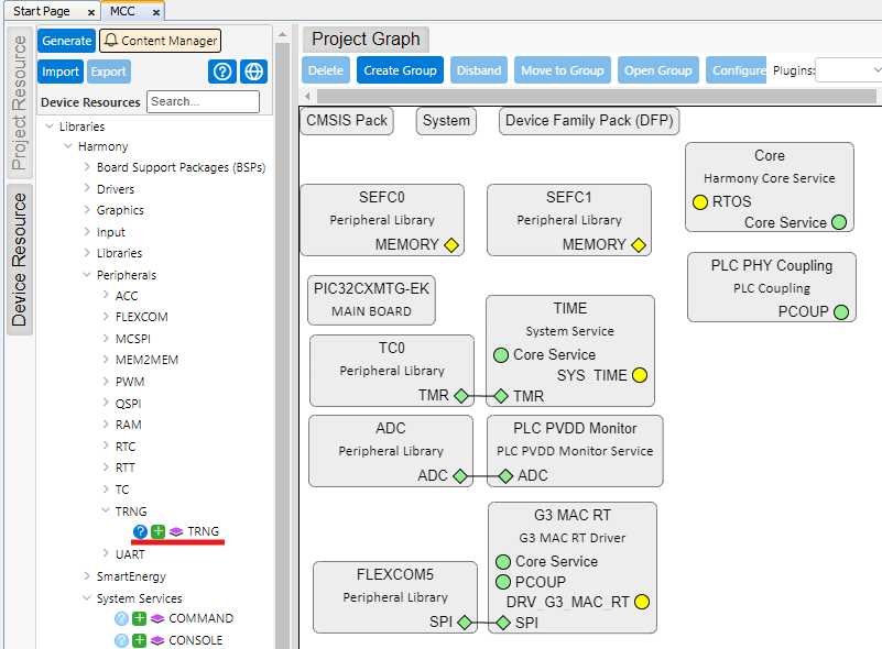
Add TRNG component from Peripherals
section. This will be used in this example for Random Number generation.Figure 2-15. Add TRNG Component
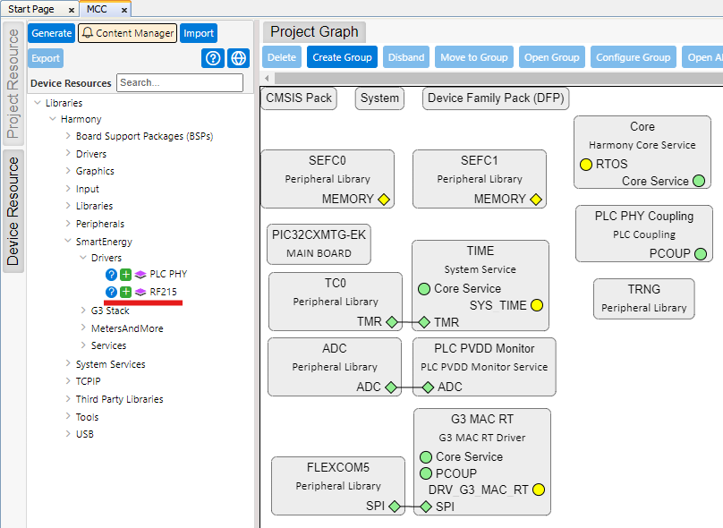
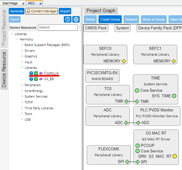
Add and Configure RF215 component:
Navigate to Drivers Section
inside SmartEnergy and add RF215 component by clicking the Green Plus
sign.Figure 2-16. Add RF215
Component
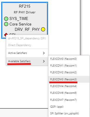
Right-click the SPI
dependency and select Available Satisfiers>FLEXCOM3
(flexcom3).Figure 2-17. Select FLEXCOM3
for SPI
FLEXCOM3 component is
auto-configured when connected to RF215 component.
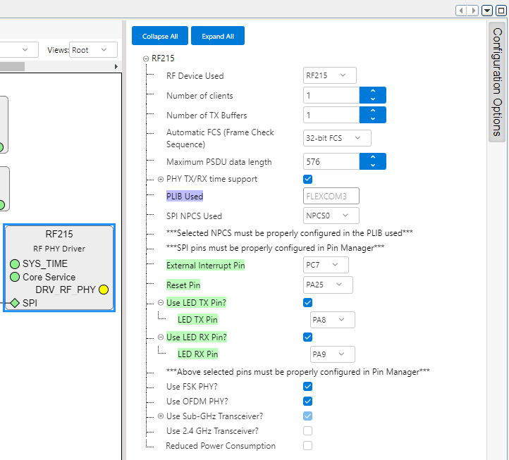
Click the RF215 component, on
Configuration Options set Pins so configuration matches the following:Figure 2-18. RF215
Configuration
Add and configure Cryptographic
Library:
Navigate to Libraries Section
and add Crypto_v4 component by clicking the Green Plus sign.Figure 2-19. Add Crypto Library
Component
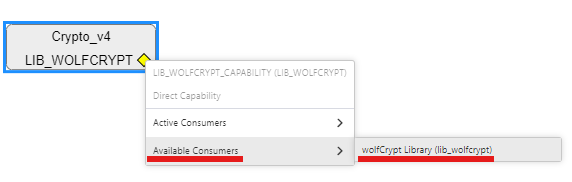
Right-click the LIB_WOLFCRYPT
dependency and select Available Consumers>wolfCrypt Library
(lib_wolfcrypt).Figure 2-20. Select wolfCrypt
for LIB_WOLFCRYPT
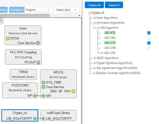
Click the Crypto_v4
component, on Configuration Options enable Security options required by G3
and supported by HW on the MCU, as seen on the figure:Figure 2-21. Crypto_v4
Configuration
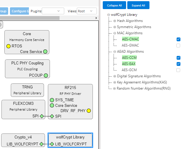
Do the same on wolfCrypt
Library component to select the required Security options using SW
implementation:Figure 2-22. wolfCrypt
Configuration
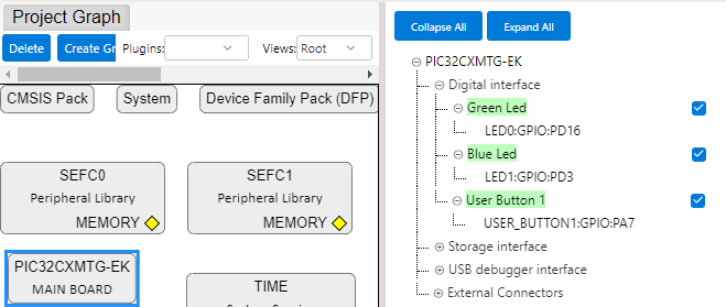
Finally, on PIC32CXMTG-EK component,
enable the use of LEDs and User Button.Figure 2-23. Enable LEDs and Button on
PIC32CXMTG-EK