
4.5.3.1 AC Signal With No Noise
- ADC2 computation mode: Average mode
- Input signal: AC 1V peak-to-peak, frequency 50 Hz and offset at 1.25V
- Press push button S1 on the HPC board
- Verify the computation mode number in the Data Visualizer graph is 3
- Verify that LED D3 is illuminated
- Configure the Signal & Noise Generator to generate a sine wave of amplitude ~1V, frequency 50 Hz and offset at 1.25V
- Disable the random noise
- Verify the input signal using an
oscilloscope. The expected result is as shown in Figure 4-9
Figure 4-9. AC Signal Oscilloscope Capture 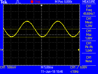
The Data Visualizer graph is as shown in Figure 4-10. The red colored signal is an AC input signal (ADRES value), the green colored signal is a filtered signal (ADFLTR value).
The average voltage of a periodic waveform whose two halves are exactly similar, either sinusoidal or non-sinusoidal, will be the mean of VMAX and VMIN over one complete cycle.
Sine waves are symmetrical about time axis, thus average is zero: positive area cancels negative area.
From the Figure 4-10 it can be seen that the average result of the AC signal is approaching the offset value. In the example source code the averaging has been done with 32 samples as ADCRS bits configured to 5 and ADC auto conversion trigger is at every 625 μs. The advantage here is that the sample accumulation and averaging handling is not needed in code as ADACC and ADFLTR registers are available.
Average value calculation of an AC signal depends upon the number of equidistant samples accumulated in a cycle and the sampling frequency and frequency of the input signal.
To calculate the correct average value of 50 Hz (20 ms) signal over the full cycle with 32 equidistant samples, the sampling frequency should be, 20 ms/32 = 625 μs (1.6 kHz).
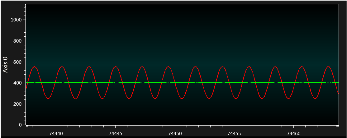
As the input sine signal has an offset of 1.29V, the average value of the sine signal is the offset with ADC count 400 (1023 x 1.29/3.3 =399).
Pros: Using this mode, the ADACC register gives accumulated values of up to 64 samples and the ADFLTR register gives an average value of all the accumulated samples so, software overhead can be avoided.
Cons: The number of samples to be accumulated is limited to 64.