2.10.3.4 Step 4: Results
(Ask a Question)Observe the following results:
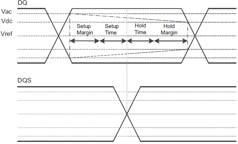
- Setup and hold time between data signals and the respective DQS over all corners.
- Setup and hold time between Control/Command/Address signals and the clock over all corners.
Overshoot and undershoot of all signals with respect to JEDEC specifications over all corners, and also DC threshold multi crossing that is due to the excessive ringing.
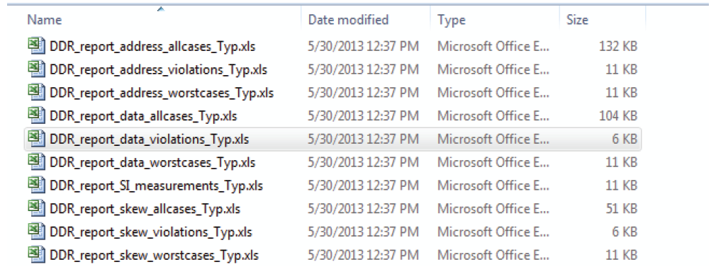
The simulation tool generates the report where all the details are available. For example, Hyperlynx generates the set of excel sheets which contain all setup and hold margin, overshoot, and undershoot information for all corners. It also generates driver and receiver waveforms for all the nets.
The following figure shows the file list where all the information regarding the simulation are stored.
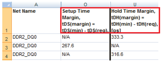
The reports give setup and hold time for each net and also signal integrity details where overshoot and undershoots are mentioned. The following figure shows the example of report for DQ0 net. It also shows that the DQ0 has enough setup and holds time margins.
If any of the net is violating the setup and holding time margins, the length of the net must be changed accordingly. If there is any high peak overshoot or undershoot, it might be because of the high value termination resistor. Adjust the value of ODT and re-iterate the simulation.
The following figure shows how to look at setup and hold time margins for DQ and DQS signals. The same is applicable to margin between the Command/Control/Address and CLK signals.