2.8 Buffer Schematic for Single-Ended Inputs on 62EM1 Gate Driver
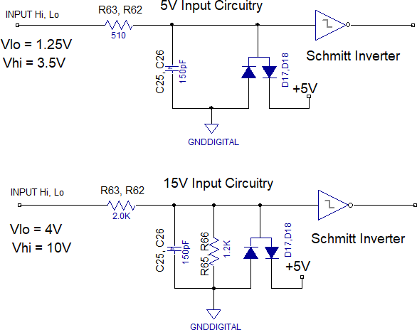
The following figure shows the input buffers schematics for 5V and 15V logic.

The following figure shows the input buffers schematics for 5V and 15V logic.

The online versions of the documents are provided as a courtesy. Verify all content and data in the device’s PDF documentation found on the device product page.