2.7 Pinout—Main-to-Secondary Driver Connectors
The following tables list the details of pinout—main-to-secondary driver connectors.
|
Pin No. |
Signal |
|---|---|
1 | Positive supply voltage1 |
2 | HI drive in |
3 | Negative supply voltage1 |
4 | GND |
Note:
- Positive and negative supply voltages provided by the main gate driver to the secondary gate driver.
|
Pin No. |
Signal |
|---|---|
1 | Positive supply voltage1 |
2 | LO drive in |
3 | Negative supply voltage1 |
4 | GND |
5 | NC—no connect |
Note:
- Positive and negative supply voltages provided by the main gate driver to the secondary gate driver.
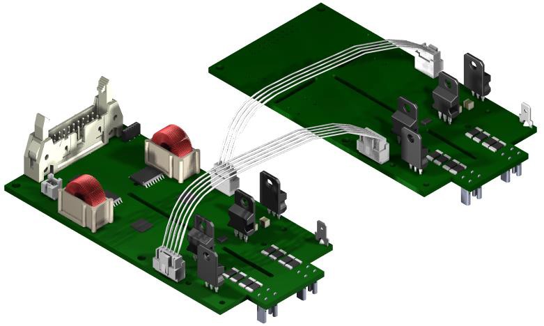
The following figure shows the typical main-secondary setup.