2.6 Recommended Interface Circuitry
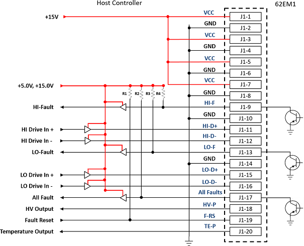
The following figure shows the 20-pin pinout diagram for the gate driver.

The following figure shows the 20-pin pinout diagram for the gate driver.

The online versions of the documents are provided as a courtesy. Verify all content and data in the device’s PDF documentation found on the device product page.