
5.1.1.2 BLE Legacy Scan
This section helps users to enable the BLE Scanning on the WBZ351 Curiosity board using MCC. BLE scanning is utilized to detect devices that are in advertising mode. Within BLE protocols, the process is initiated by either a central device or an observer engaging in scanning activities.
Users can choose to either run the precompiled Application Example hex file provided on the WBZ351 Curiosity Board or follow the steps to develop the application from scratch.
It is recommended to follow the examples in sequence to understand the basic concepts before progressing to the advanced topics.
Recommended Readings
-
Getting Started with Application Building Blocks – See Building Block Examples from Related Links.
-
Getting Started with Central Building Blocks – See Central Devices from Related Links.
-
FreeRTOS and BLE Stack Setup – See Central - FreeRTOS BLE Stack and App Initialize from Related Links.
- See BLE Legacy Scan from Related Links.
- See BLE Connection from Related Links.
-
BLE Software Specification – See MPLAB® Harmony Wireless BLE in Reference Documentation from Related Links.
Hardware Requirement
| S. No. | Tool | Quantity |
|---|---|---|
| 1 | WBZ351 Curiosity Board | 1 |
| 2 | Micro USB cable | 1 |
SDK Setup
Refer to Getting Started with Software Development from Related Links.
Software
To install Tera Term tool, refer to the Tera Term web page in Reference Documentation from Related Links.
Smartphone Application
None.
Programming the Precompiled
.hex File or Application Example
Using MPLAB® X IPE:
-
Import and program the precompiled hex file:
<Discover Path>\wireless_apps_pic32cxbz3_wbz35\apps\ble\building_blocks\central\legacy_scan\hex - For detailed steps, refer to
Programming a Device in MPLAB® IPE in Reference
Documentation from Related Links.Note: Ensure to choose the correct Device and Tool information.
Using MPLAB® X IDE:
- Perform the following the steps mentioned in Running a Precompiled Example. For more information, refer to Running a Precompiled Application Example from Related Links.
-
Open and program the application:
legacy_scan.Xlocated in<Discover Path>\wireless_apps_pic32cxbz3_wbz35\apps\ble\building_blocks\central\legacy_scan\firmware - For more details on how to find the Discover path, refer to Download Application Example from Discover in Running a Precompiled Application Example from Related Links.
Demo Description
This application example enables users to perform passive scanning. After programming the application example, upon Reset, the user can see the beginning of scan operation. The device scans the Bluetooth® addresses over the next 10 seconds. After 10 seconds, the device completes the scanning operation.
Testing
- Programming the WBZ351 Curiosity Board
- Using a micro USB cable, connect the Debug USB on the WBZ351 Curiosity board to a PC.
- Program the board
with the precompiled hex file or application example. The hex file
for passive scanning is located in
<Discover
                    Path>\wireless_apps_pic32cxbz3_wbz35\apps\ble\building_blocks\central\legacy_scan\hex
- Setting Up Tera Term
Terminal
- Open Tera Term on the
PC and configure the serial terminal with the following settings:
- Baud Rate/Speed – 115200 (as configured in SERCOM configuration)
- Parity – None
- Data Bits – 8
- Stop Bits – 1
- Flow Control – None
- Open Tera Term on the
PC and configure the serial terminal with the following settings:
- Running the Scan
- Reset the WBZ351 Curiosity Board.
- Upon reset, the user
must see the message
Scanningdisplayed on Tera Term, indicating the start of the scan operation. - The WBZ351 Curiosity Board performs a passive
scanning for 10 seconds. During this time, it displays the Bluetooth
addresses of all devices advertising on BLE channels 37, 38 and
39.
Figure 5-11. BLE Scanning TeraTerm 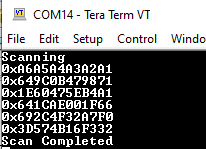
- Scan Completion
- After 10 seconds, the
Tera Term displays
Scan Completedmessage, indicating the end of the scan operation.
- After 10 seconds, the
Tera Term displays
- Bluetooth Low Energy
Advertising Test
- For a complete test, use another WBZ351 Curiosity Board configured as a Bluetooth Low Energy Advertiser.
- Set the desired Bluetooth address on the advertising board.
- The scanning board detects and displays the address of the advertising board during the scan window. For more details, refer to the BLE Sleep Mode Legacy Advertisements from Related Links.
Developing this Application from Scratch Using MCC
-
Create a new harmony project. For more details, see Creating a New MCC Harmony Project from Related Links.
- Import component configuration
-This step helps users setup the basic components and configuration required to
develop this application. The imported file is of format
.mc4and is located in the path<Discover Path>\wireless_apps_pic32cxbz3_wbz35\apps\ble\building_blocks\central\legacy_scan\firmware\legacy_scan.X - Accept Dependencies or
Satisfiers.
- If prompted to resolve dependencies or add required modules. Click Yes.
- MPLAB® MCC automatically adds any required drivers or middleware.
- Verify Project GraphIn Project Graph window, confirm that all expected components are present. For more details, see the following figure.
Figure 5-12. Project Graph 
Verifying the Scan Configuration
- Open the Project Graph
- In MPLAB® X IDE, with MCC open, locate the Project Graph tab. In the Project Graph tab, the user can see all the components and their relationships to the project.
- Select the BLE Stack
Component
- Click on the BLE Stack component in project graph. This opens the “BLE Stack” component Configuration Options tab.
- In the “BLE Stack” Configuration Options tab, the user can set the parameters as per the requirement as illustrated in the following figure.
Figure 5-13. BLE Stack Configuration 
Generating a Code
For more details on code generation, refer to MPLAB Code Configurator (MCC) Code Generation from Related Links.
Files and Routines Automatically generated by the MCC

Initialization.c
app_ble.c
app_ble.c
| Source Files | Usage |
|---|---|
app.c | Application State machine, includes calls for Initialization of all BLE stack (GAP,GATT, SMP, L2CAP) related component configurations |
app_ble\app_ble.c | Source Code for the BLE stack related component
configurations, code related to function calls from
app.c |
app_ble\app_ble_handler.c | All GAP, GATT, SMP and L2CAP event handlers |
|
Note:
app.c is auto-generated and has a state
machine based application code sample. The users can use
this template to develop their application. | |
ble_gap.h: This header file contains BLE GAP functions and is automatically included in theapp.cfile.
- MCC generates and adds the
code to initialize the BLE Stack GAP, GATT, L2CAP, and SMP in
APP_BleStackInit()function. APP_BleStackInit()is the API that is called inside the application’s Initialization stateAPP_STATE_INITinapp.c.
User Application Development
- Include
- Include the user action. For more information, refer to User Action from Related Links.
definitions.hin all the files where UART will be used to print debug information.Note: Includedefinitions.hin all application source files where the user can exercise peripheral functionality, as it is not specific to just the UART peripheral.
- Start
Scanning
// Scanning Enabled
BLE_GAP_SetScanningEnable(true, BLE_GAP_SCAN_FD_ENABLE, BLE_GAP_SCAN_MODE_OBSERVER, 100);
// Output the status string to UART
SERCOM0_USART_Write((uint8_t *)"Scanning \r\n", 11);
- The user can call
this API in the application’s initialization state,
APP_STATE_INIT, inapp.c. The scan duration is 10 seconds.Figure 5-18. app.c
- The user can call
this API in the application’s initialization state,
- Scan Results
BLE_GAP_EVT_ADV_REPORTevent is generated upon finding advertisements on legacy channels// code snippet to print scan results uint8_t scanAddr[12]; //var to store ASCII address BLE_GAP_EvtAdvReport_T scanResults; scanResults.addr = p_event->eventField.evtAdvReport.addr; APP_HexToAscii(6, scanResults.addr.addr, scanAddr); SERCOM0_USART_Write((uint8_t *)"0x", 2); SERCOM0_USART_Write((uint8_t *)scanAddr, 12); SERCOM0_USART_Write((uint8_t *)"\r\n", 2);
// function to convert HEX to ASCII
static void APP_HexToAscii(uint8_t byteNum, uint8_t *p_hex, uint8_t *p_ascii)
{
    uint8_t i, j, c;
    uint8_t digitNum = byteNum * 2;

    if (p_hex == NULL || p_ascii == NULL)
        return;

    for (i = 0; i < digitNum; i++)
    {
        j = i / 2;
        c = p_hex[j] & 0x0F;

        if (c >= 0x00 && c <= 0x09)
        {
            p_ascii[digitNum - i - 1] = c + 0x30;
        }
        else if (c >= 0x0A && c <= 0x0F)
        {
            p_ascii[digitNum - i - 1] = c - 0x0A + 'A';
        }

        p_hex[j] /= 16;
    }
}
- Add the preceding
code to the appropriate sections within the
app_ble_handler.cFigure 5-19. app_ble_handler.c
- Scan Timeout Event
- In
app_ble_handler.c,BLE_GAP_EVT_SCAN_TIMEOUTevent is generated when BLE Scan duration expires.- Add the
following code, inside
BLE_GAP_EVT_SCAN_TIMEOUTcase.SERCOM0_USART_Write((uint8_t *)”Scan Completed \r\n”, 17);
Figure 5-20. app_ble_handler.c
- Add the
following code, inside
Note: The users can exercise various other BLE Advertisement functionalities. For more information, refer to MPLAB Harmony Wireless BLE in Reference Documentation from Related Links. - In
Where to go from Here
See BLE Connection from Related Links.