
5.1.1.4 BLE Connection
- Advertiser (Transmitting Connectable Adv)
- Scanner
Users can choose to either run the precompiled Application Example hex file provided on the WBZ351 Curiosity Board or follow the steps to develop the application from scratch.
It is recommended to follow the examples in sequence to understand the basic concepts before progressing to the advanced topics.
Recommended Readings
-
Getting Started with Application Building Blocks – See Building Block Examples from Related Links.
-
Getting Started with Central Building Blocks – See Central Devices from Related Links.
-
FreeRTOS and BLE Stack Setup – See Central - FreeRTOS BLE Stack and App Initialize from Related Links.
- See BLE Legacy Scan from Related Links.
- See BLE Connection from Related Links.
- See BLE Transparent UART from Related Links.
-
BLE Software Specification – See MPLAB® Harmony Wireless BLE in Reference Documentation from Related Links.
Hardware Requirement
| S. No. | Tool | Quantity |
|---|---|---|
| 1 | WBZ351 Curiosity Board | 2 |
| 2 | Micro USB cable | 2 |
SDK Setup
Refer to Getting Started with Software Development from Related Links.
Software Requirement
To install Tera Term tool, refer to the Tera Term web page in Reference Documentation from Related Links.
Smartphone Application
None
Programming the Precompiled Hex File or Application Example
Using MPLAB® X IPE:
- Central Device – Import and program the
precompiled hex file:
<Discover Path>\wireless_apps_pic32cxbz3_wbz35\apps\ble\building_blocks\central\central_conn\hex - Peripheral Device – Import and program
the precompiled hex file:
<Discover Path>\wireless_apps_pic32cxbz3_wbz35\apps\ble\building_blocks\Peripheral\Peripheral_conn\hex - For detailed steps, refer to
Programming a Device in MPLAB® IPE in Reference
Documentation from Related Links.Note: Ensure to choose the correct Device and Tool information.
Using MPLAB® X IDE:
- Perform the following the steps mentioned in Running a Precompiled Example. For more information, refer to Running a Precompiled Application Example from Related Links.
- Central Device – Open and program the
application
central_conn.Xlocated in<Discover Path>\wireless_apps_pic32cxbz3_wbz35\apps\ble\building_blocks\central\central_conn\firmware - Peripheral Device – Open and program the
application
peripheral_conn.Xlocated in<Discover Path>\wireless_apps_pic32cxbz3_wbz35\apps\ble\building_blocks\peripheral\peripheral_conn\firmware -
For more details on how to find the Discover path, refer to Download Application Example from Discover in Running a Precompiled Application Example from Related Links.
Demo Description
Scanning– At the initiation of the scan process.Connected!– Upon successful connection.Disconnected– When the connection is lost, within a terminal emulator interface.
- Baud Rate/Speed – 115200 (as configured in SERCOM configuration)
- Parity – None
- Data Bits – 8
- Stop Bits – 1
- Flow Control – None
Testing
Users must use another WBZ351 Curiosity Board configured as peripheral connection, see BLE Connection from Related Links.
This section assumes that a user has already programmed the
peripheral_conn and central_conn application on two WBZ351 Curiosity Boards.
- Board 1 – WBZ351 Curiosity Board programmed with
peripheral_conn.- Open TeraTerm and configure as
mentioned below:Terminal Settings
- Baud Rate/Speed – 115200 (as configured in SERCOM configuration)
- Parity – None
- Data Bits – 8
- Stop Bits – 1
- Flow Control – None
- Reset the board. Upon reset, the
Advertisingmessage appears on the Tera Term.
- Open TeraTerm and configure as
mentioned below:
- Board 2 – WBZ351 Curiosity Board programmed with
central_conn.- Open TeraTerm and configure as
mentioned below:
Terminal Settings
- Baud Rate/Speed – 115200 (as configured in SERCOM configuration)
- Parity – None
- Data Bits – 8
- Stop Bits – 1
- Flow Control – None
- Reset the board. Upon reset, the
Scanningmessage appears on the Tera Term. - Upon finding peripheral device with public address {0xA1, 0xA2, 0xA3, 0xA4, 0xA5,
0xA6} message
Found Peer Nodewill be displayed and a connection request will be initiatedInitiating Connection.
- Open TeraTerm and configure as
mentioned below:
Connected! message on respective terminal windows.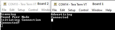
Developing the Application from Scratch using MCC
- Create a new harmony project. For more details, see Creating a New MCC Harmony Project from Related Links.
- Import Component Configuration - This
step helps users to setup the basic components and configuration required to develop this
application. The imported file is of format
.mc4and is located in the path<Discover Path>\wireless_apps_pic32cxbz3_wbz35\apps\ble\building_blocks\central\central_conn\firmware\central_conn.X.Note: Import and export functionality of component configuration helps users to start from a known working setup of MCC configuration. - Accept Dependencies or Satisfiers.
- If prompted to resolve dependencies or add required modules. Click Yes.
- MPLAB® MCC automatically adds any required drivers or middleware.
- Verify Project Graph.

Verifying Scan and Connection Configuration
- Open the Project Graph
- In MPLAB® X IDE, with MCC open, locate the Project Graph tab. In the Project Graph tab, the user can see all the components and their relationships to the project.
- Select the BLE Stack Component
- Click on the BLE Stack component in project graph. This opens the “BLE Stack” component Configuration Options tab.
- In the “BLE Stack” Configuration
Options tab, the user can set the parameters as per the requirement illustrated
in the following figure.
Figure 5-32. BLE Stack Configuration 
Generating a Code
For more details on code generation, refer to MPLAB Code Configurator (MCC) Code Generation from Related Links.
Files and Routines Automatically generated by the MCC

initialization.c
app_ble.c
| Source Files | Usage |
|---|---|
app.c | Application State machine, includes calls for Initialization of all BLE stack (GAP,GATT, SMP and L2CAP) related component configurations |
app_ble\app_ble.c | Source Code for the BLE stack related component configurations, code related
to function calls from app.c |
app_ble\app_ble_handler.c | All GAP, GATT, SMP and L2CAP Event handlers |
|
Note:
app.c is autogenerated and has a
state machine based Application code sample. Users can use this template to
develop their application. | |
- Header Files
ble_gap.h: This header file contains BLE GAP functions and is automatically included in theapp.cfile.
- Function Calls
- MCC generates and adds the code to
initialize the BLE Stack GAP, GATT, L2CAP and SMP in the
APP_BleStackInit()function. APP_BleStackInit()is the API that will be called inside the application’s Initial stateAPP_STATE_INITinapp.c.
- MCC generates and adds the code to
initialize the BLE Stack GAP, GATT, L2CAP and SMP in the
User Application Development
- Include the user action. For more information, refer to User Action from Related Links.
definitions.hin all the files where UART will be used to print debug information.Note:Start Scanningdefinitions.his not specific to just UART peripheral, instead it must be included in all application source files where peripheral functionality will be exercised.// Scanning Enabled BLE_GAP_SetScanningEnable(true, BLE_GAP_SCAN_FD_ENABLE, BLE_GAP_SCAN_MODE_OBSERVER, 1000); // Output the state string to UART SERCOM0_USART_Write((uint8_t *)"Scanning \r\n", 11);
- This API is called in the application’s Initial state,
APP_STATE_INIT, inapp.c. The scan duration is 100 seconds.Figure 5-36. app.c
- Scan Results and Initiating a BLE
connection
BLE_GAP_EVT_ADV_REPORTevent inapp_ble_handler.cis generated upon finding advertisements on legacy channels.- The user can initiate a BLE
connection by using the
BLE_GAP_CreateConnection(&createConnParam_t);API.// code snippet to filter scan results and initiate connection if (p_event->eventField.evtAdvReport.addr.addr[0] == 0xA1 && p_event->eventField.evtAdvReport.addr.addr[1] == 0xA2) { SERCOM0_USART_Write((uint8_t *)"Found Peer Node\r\n", 17); BLE_GAP_CreateConnParams_T createConnParam_t; createConnParam_t.scanInterval = 0x3C; // 37.5 ms createConnParam_t.scanWindow = 0x1E; // 18.75 ms createConnParam_t.filterPolicy = BLE_GAP_SCAN_FP_ACCEPT_ALL; createConnParam_t.peerAddr.addrType = p_event->eventField.evtAdvReport.addr.addrType; memcpy(createConnParam_t.peerAddr.addr, p_event->eventField.evtAdvReport.addr.addr, GAP_MAX_BD_ADDRESS_LEN); createConnParam_t.connParams.intervalMin = 0x10; // 20ms createConnParam_t.connParams.intervalMax = 0x10; // 20ms createConnParam_t.connParams.latency = 0; createConnParam_t.connParams.supervisionTimeout = 0x48; // 720ms SERCOM0_USART_Write((uint8_t *)"Initiating Connection\r\n", 23); BLE_GAP_CreateConnection(&createConnParam_t); }
Figure 5-37. app_ble_handler.c
- Connected and Disconnected
Events
- All the possible GAP, GATT, SMP and
L2CAP Event handlers are available in the
app_ble_handler.cfile, the users can implement application code to denote Connection state here.BLE_GAP_EVT_CONNECTEDevent is generated after a successful BLE connection with peripheral device.// Connected EVT SERCOM0_USART_Write((uint8_t *)"Connected!\r\n", 12); //Disconnected EVT SERCOM0_USART_Write((uint8_t *)"Disconnected\r\n", 15);
Figure 5-38. app_ble_handler.c
- All the possible GAP, GATT, SMP and
L2CAP Event handlers are available in the
- Scan Timeout Event
- In
app_ble_handler.c,BLE_GAP_EVT_SCAN_TIMEOUTevent is generated when BLE scan duration expires.SERCOM0_USART_Write((uint8_t *)"Scan Completed\r\n", 17);Figure 5-39. app_ble_handler.c
Note: The users can exercise various other BLE Advertisement functionalities using the BLE Stack APIs. For more information, refer to BLE Stack in Reference Documentation from Related Links. - In
Where to go from Here
See BLE Transparent UART from Related Links.