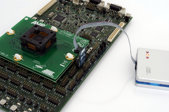
3.1.1 Using the JTAG 10-pin Connector
The pinout for the 10-pin JTAG connector is shown in Figure 4-2.
Be sure to use the correct orientation of the 10-pin header when connecting the JTAGICE3 to the target application PCB. The red wire on the probe cable indicates PIN1, as does the 'dot' on the 100-mil adapter.

