3.5.2.7 Inferring a Line Buffer
(Ask a Question)A line buffer is used to buffer a line of pixels of an image or a video frame, in order to keep data around and reduce the overall required memory bandwidth. It is useful for image/video processing applications, where an image/video pixel is continuously streamed in and processed.
SmartHLS™ provides a LineBuffer C++ template class that can be used to conveniently infer a line buffer hardware structure. For usages about the LineBuffer class, please refer to 3.5.1.17.8.1 Line Buffer in the User Guide. This section will give more details about the motivations of using a line buffer and its underlying implementation.
A good example of using a line buffer is the Sobel filter, which is used as one of the key steps of edge detection – a widely used transformation that identifies the edges in an input image and produces an output image showing just those edges. At a high-level, Sobel filtering involves applying a pair of two 3×3 convolutional kernels (or filters), typically called Gx and Gy, to a 3x3 pixel stencil window. The stencil window slides over the entire image from left to right, and top to bottom, as shown below. The two kernels detect the edges in the image in the horizontal and vertical directions. At each position in the input image, the filters are applied separately and the computed values are combined together to produce a pixel value in the output image.
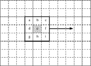
At every position of the stencil, we calculate the edge value of the middle pixel e, using the adjacent pixels labeled from a to i, each of which is multiplied by the value at its corresponding position of Gx and Gy, and then summed. An example C code for the Sobel filter is shown below.
#define HEIGHT 512
#define WIDTH 512

for (y = 0; y < HEIGHT; y++) {
    for (x = 0; x < WIDTH; x++) {
        if (notinbounds(x,y)) continue;
        xdir = 0; ydir = 0;
        for (xOffset = -1; xOffset <= 1; xOffset++) {
            for (yOffset = -1; yOffset <= 1; yOffset++) {
                pixel = input_image[y+yOffset][x+xOffset];
                xdir += pixel * Gx[1+xOffset][1+yOffset];
                ydir += pixel * Gy[1+xOffset][1+yOffset];
            }
        }
        edgeweight = bound(xdir) + bound(ydir);
        output_image[y][x] = 255 - edgeweight;
    }
}
The outer two loops ensure that we visit every pixel in the image, while ignoring image borders. The stencil gradient calculation is performed in the two inner loops. The x and y directions are bound to be between 0 and 255 and the final edge value is stored to the output image.
Consider a case where each pixel in a 512x512 image is received every clock cycle. One approach to implementing this in hardware is to store the entire image in memory, then perform filtering on the image by loading it from memory. While this approach is certainly possible, it suffers from several weaknesses. First, if the input image is 512×512 pixels, with each pixel received every clock cycle, it would take 262,144 cycles to store the entire image. This represents a significant wait time before seeing any output. Second, we would need to store the entire input image in memory. Assuming 8-bit pixel values, this would require 262KB of memory. If the image is stored in off-chip memory, it would take a considerable amount of time to access each pixel, and the performance would suffer significantly.
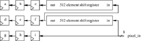
The figure shows two buffers, each holding 512 pixels. Rather than storing the entire input image, we only need to store the previous two rows of the input image (as the 3x3 stencil window can cover 3 rows), along with a few pixels from the first row being covered by the stencil window. As new pixels are received, they are stored into the line buffers. Once the first two lines of the image (and the first three pixels of the third row) have been received, we can start computing the edges. From this point onwards, the stencil starts to move with every new pixel received. When the stencil moves to the next row, its previous two rows are always stored in the line buffers.
With the line buffers, we can start computing the edges much earlier, as we do not have to wait for the entire image to be stored. This also drastically reduces the amount of memory required to just two rows of the input image. By storing the line buffers in on-chip memory, its data can be accessed very quickly (with 1 cycle latency). Techniques such as this allow efficient real-time video processing on FPGAs.
To give more insight to SmartHLS's LineBuffer class, the code snippet below illustrates the LineBuffer template class implementation when it is instantiated with an 3x3 WindowSize.
template <typename PixelType, unsigned ImageWidth
          /* WindowSize == 3 for illustration purpose */>
class LineBuffer {
  private:
    // Two line buffers storing two rows of pixels.
    PixelType prev_rows[2][ImageWidth];
    // Index to keep track of the current index in row (along x-axis).
    unsigned prev_row_index{0};

  public:
    // The 3x3 stencil window.
    PixelType window[3][3];

    void ShiftInPixel(PixelType input_pixel) {
        // Shift existing window to the left by one.
        window[0][0] = window[0][1];   window[0][1] = window[0][2];
        window[1][0] = window[1][1];   window[1][1] = window[1][2];
        window[2][0] = window[2][1];   window[2][1] = window[2][2];

        // Grab next column (the rightmost column of the sliding window).
        window[0][2] = prev_rows[1][prev_row_index];
        window[1][2] = prev_rows[0][prev_row_index];
        window[2][2] = input_pixel;

        // Update the line buffers.
        prev_rows[1][prev_row_index] = prev_rows[0][prev_row_index];
        prev_rows[0][prev_row_index] = input_pixel;

        prev_row_index = (prev_row_index == ImageWidth - 1) ? 0 : prev_row_index + 1;
    }
};
This class contains two internal line buffers using a private 2xImageWidth prev_rows array, and an externally accessible 3x3 stencil window. The prev_row_index variable keeps track of the position of the line buffer where its data needs to shifted out, and where new data needs to be shifted in.
Each time when the ShiftInPixel method is called to shift in a new input_pixel, we shift each element in the 3x3 window to the left by one. The last elements of the line buffers are read out and stored into the rightmost column of the 3x3 window, along with the new input pixel. The new input pixel is also stored into the first line buffer, while the last element of the first line buffer is stored into the second line buffer. Then prev_row_index is updated, by incrementing it by one, unless it has gone through the entire row, in which case it is set to zero (indicating that we are moving onto a new row).
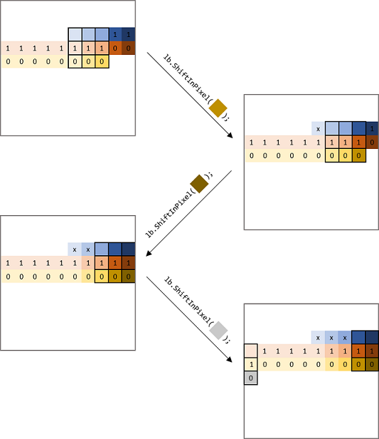
To help visualizing how the window and line buffers are updated, the diagram below shows a 3x3 window sliding across a 10x10 input image. We declare a LineBuffer as hls::LineBuffer<PixelType, 10, 3> lb;. The outer box represents the 10x10 input image, and the 3x3 black box represents the sliding window. The pixels labelled "0" are stored in the first line buffer prev_rows[0] in the code above), and the pixels labelled "1" are stored in the second line buffer (e.g., prev_rows[1]). When the ShiftInPixel method is called to shift in a new pixel, you can see the 3x3 window is shifted to left and covers the new pixel. The line buffers are also updated --- prev_rows[0] takes in the new pixel and retires its oldest pixel, which is taken in by the second line buffer prev_rows[1]; prev_rows[1] also retires its oldest pixel, labelled with "x".