11.4 Floorplanner View Window
(Ask a Question)The Floorplanner View window displays all design elements in one window. The selections you make in the views are reflected in the Floorplanner View. The color scheme used in the canvas depends on the Layers and Colors you have selected in the Display Options window.

11.4.1 Operating Modes
(Ask a Question)The Floorplanner View has two modes of operation:
- Macro Manipulation Mode. Use this mode to work with macros, such as assigning macros to location or unassigning placed macros from locations. You can also view properties of selected macros in the Floorplanner View from the properties window. You can select multiple macros from the Floorplanner View by pressing the CTRL key and selecting required macros in the Floorplanner View.
- Region Manipulation Mode. Use this mode to work on regions such as resizing, renaming, or deleting regions, or assigning and unassigning macros or nets to regions.
Click the Macro Manipulation Mode or Region Manipulation Mode button to switch between modes.
11.4.2 Floorplanner View Icons
(Ask a Question)The icons available at the top of the Floorplanner View window allow you to zoom in, zoom out, assign I/ O banks, runs DRC checks, and create regions for placement.

| Icon | Name | Function |
|---|---|---|
 |
Rubber Band Zoom | Drags out an area to enlarge (zoom) into. |
 |
Rubber Band Select | Zooms into an area. Click in the Floorplanner
View and drag the mouse to delineate an area. Release the mouse and all macros
inside the delineated area are selected. Works in the Macro Manipulation Mode. |
 |
Zoom In | Zooms in to Floorplanner View. |
 |
Zoom Out | Zooms out of Floorplanner View. |
 |
Zoom to Fit | Zooms to fit the Floorplanner View. |
 |
Zoom to Location | Zooms to a location specified by X-Y coordinates. |
 |
Zoom to fit Selection | Zooms to fit selected macros and ports. When enabled, the view is centered on the selected and placed ports. |
 |
Check Design Rules | Runs the Prelayout Checker, a preliminary check of the netlist for possible Place and Route issues. |
 |
Check DRC Rules for Selected Interfaces | Run the Prelayout Checker for the selected interface, a preliminary check of the netlist for possible Place and Route issues. |
 |
I/O Bank Settings | Sets the I/O bank to specific I/O Technology. |
 |
Auto Assign I/O Bank | Runs the Auto I/O Bank and Globals Assigner. Assigns a voltage to every I/O Bank that does not have a voltage assigned to it and if required, a VREF pin. |
 |
Create Empty | Creates an empty user region. |
 |
Create Inclusive | Creates an inclusive user region. |
 |
Create Exclusive | Creates an exclusive user region. |
 |
Delete Region | Deletes the user-created region you selected. |
  |
Use the Macro Manipulation Mode and Region Manipulation Mode buttons | Click the Macro Manipulation Mode and Region Manipulation Mode buttons to switch modes. |
 |
Zoom Floorplanner View To Fit | Zooms to fit the Floorplanner View. |
 |
Expand Floorplanner View To Minimum Zoom | Expands the floorplanner view to make devices visible. |
 |
View Full Screen | Toggle button to view full screen and restore back. |
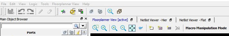
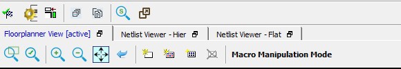
11.4.3 Netlist Viewer in Floorplanner View Window
(Ask a Question)In addition to the Chip View, the Floorplanner View window displays the netlist views. See Netlist Views for details.
The Floorplanner View and the Netlist View feature different sets of icons specific to their views. There is also a Floorplanner View/Netlist Viewer menu that toggles between Floorplanner View and Netlist View based on the view that is active at the time. See the following figures.