
16.1.9 MACC_PA
(Ask a Question)The MACC_PA macro implements multiplication, multiply-add, and multiply-accumulate functions. The MACC_PA block can accumulate the current multiplication product with a previous result, a constant, a dynamic value, or a result from another MACC_PA block. Each MACC_PA block can also be configured to perform a Dot-product operation. All the signals of the MACC_PA block have optional registers.
16.1.9.1 Features
(Ask a Question)The main features of the MACC_PA block are as follows:
- Native 18 x 18 signed multiplication and supports 17 x 17 unsigned multiplication.
- Independent third input C of data width 48 bits along with a CARRYIN, optionally registered.
- Pre-adder of B with an independent fourth input D of data width 18 bits, optionally registered.
- Internal cascade signals (48-bit CDIN and CDOUT) enable cascading of the Math blocks to support larger accumulator, adder, and subtracter without extra logic.
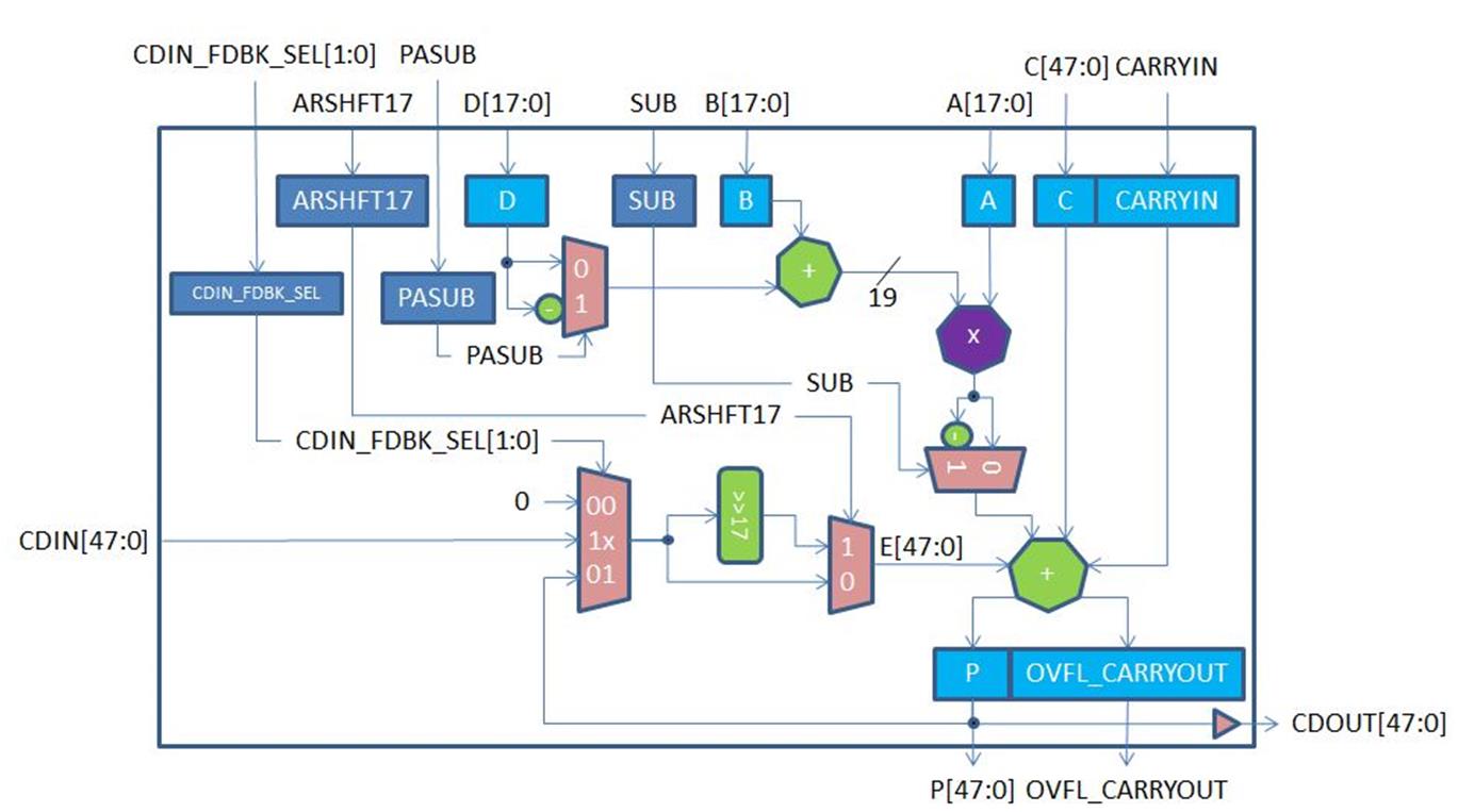
- Normal addition/subtraction: CARRYIN + C[47:0] + E[47:0] ± { ( B[17:0] ± D[17:0]) x A[17:0] }.
- Dot product mode: (B[8:0] ± D[8:0]) x A[17:9] ± (B[17:9] ± D[17:9]) x A[8:0].
- SIMD mode for dual independent multiplication of two pairs of 9-bit operands.
- Supports both registered and unregistered inputs and outputs.
- Arithmetic right-shift by 17 bits of the loopback of CDIN.
The following figure shows a simplified block diagram of the MACC_PA block.
| Port Name | Direction | Type | Polarity | Description |
|---|---|---|---|---|
| DOTP | Input | Static | High | Dot-product mode. When DOTP = 1, MACC_PA block performs Dot- product of two pairs of 9-bit operands.
|
| SIMD | Input | Static | High | SIMD mode. When SIMD = 1, MACC_PA block performs dual independent multiplication of two pairs of 9-bit operands.
|
| OVFL_CARRYOUT_SEL | Input | Static | High | Generate OVERFLOW or CARRYOUT with result P.
|
| CLK | Input | Dynamic | Rising edge | Clock for A, B, C, CARRYIN, D, P, OVFL_CARRYOUT, ARSHFT17, CDIN_FDBK_SEL, PASUB and SUB registers. |
| AL_N | Input | Dynamic | Low | Asynchronous load for A, B, P, OVFL_CARRYOUT, ARSHFT17, CDIN_FDBK_SEL, PASUB and SUB registers. Connect to 1, if none are registered. When asserted, A, B, P and OVFL_CARRYOUT registers are loaded with zero, while the ARSHFT17, CDIN_FDBK_SEL, PASUB and SUB registers are loaded with the complementary. value of the respective _AD_N. |
| A[17:0] | Input | Dynamic | High | Input data A. |
| A_BYPASS | Input | Static | High | Bypass data A registers. Connect to 1, if not registered. See Table 16-146. |
| A_SRST_N | Input | Dynamic | Low | Synchronous reset for data A registers.
Connect to 1, if not registered. See Table 16-146. |
| A_EN | Input | Dynamic | High | Enable for data A registers. Connect to 1, if not registered. See Table 16-146. |
| B[17:0] | Input | Dynamic | High | Input data B to Pre-adder with data D. |
| B_BYPASS | Input | Static | High | Bypass data B registers. Connect to 1, if not registered. See Table 16-146. |
| B_SRST_N | Input | Dynamic | Low | Synchronous reset for data B registers. Connect to 1, if not registered. See Table 16-146. |
| B_EN | Input | Dynamic | High | Enable for data B registers. Connect to 1, if not registered. See Table 16-146. |
| D[17:0] | Input | Dynamic | High | Input data D to Pre-adder with data B. When SIMD = 1, connect D[8:0] to 0. |
| D_BYPASS | Input | Static | High | Bypass data D registers. Connect to 1, if not registered. See Table 16-147. |
| D_ARST_N | Input | Dynamic | Low | Asynchronous reset for data D registers. Connect to 1, if not registered. See Table 16-147. |
| D_SRST_N | Input | Dynamic | Low | Synchronous reset for data D registers. Connect to 1, if not registered. See Table 16-147. |
| D_EN | Input | Dynamic | High | Enable for data D registers. Connect to 1, if not registered. See Table 16-147. |
| CARRYIN | Input | Dynamic | High | CARRYIN for input data C. |
| C[47:0] | Input | Dynamic | High | Input data C. When DOTP = 1, connect C[8:0] to CARRYIN. When SIMD = 1, connect C[8:0] to 0. |
| C_BYPASS | Input | Static | High | Bypass CARRYIN and C registers. Connect to 1, if not registered. See Table 16-147. |
| C_ARST_N | Input | Dynamic | Low | Asynchronous reset for CARRYIN and C registers. Connect to 1, if not registered. See Table 16-147. |
| C_SRST_N | Input | Dynamic | Low | Synchronous reset for CARRYIN and C registers. Connect to 1, if not registered. See Table 16-147. |
| C_EN | Input | Dynamic | High | Enable for CARRYIN and C registers. Connect to 1, if not registered. See Table 16-147. |
| CDIN[47:0] | Input | Cascade | High | Cascaded input for operand E. The entire bus must be driven by an entire CDOUT of another MACC_PA or MACC_PA_BC_ROM block. In Dot-product mode, the driving CDOUT must also be generated by a MACC_PA or MACC_PA_BC_ROM block in Dot-product mode. Refer to Table 16-142 to see how CDIN is propagated to operand E. |
| P[47:0] | Output | — | High | Result data. See Table 16-143. |
| OVFL_CARRYOUT | Output | — | High | OVERFLOW or CARRYOUT. See Table 16-144. |
| P_BYPASS | Input | Static | High | Bypass P and OVFL_CARRYOUT registers. Connect
to 1, if not registered. See Table 16-146. P_BYPASS must be 0 when CDIN_FDBK_SEL[0] = 1. See Table 16-142. |
| P_SRST_N | Input | Dynamic | Low | Synchronous reset for P and OVFL_CARRYOUT registers. Connect to 1, if not registered. See Table 16-146. |
| P_EN | Input | Dynamic | High | Enable for P and OVFL_CARRYOUT registers. Connect to 1, if not registered. See Table 16-146. |
| CDOUT[47:0] | Output | Cascade | High | Cascade output of result P. See Table 16-143. Value of CDOUT is the same as P. The entire bus must either be dangling or drive an entire CDIN of another MACC_PA or MACC_PA_BC_ROM block in cascaded mode. |
| PASUB | Input | Dynamic | High | Subtract operation for Pre-adder of B and D. |
| PASUB_BYPASS | Input | Static | High | Bypass PASUB register. Connect to 1, if not registered. See Table 16-145. |
| PASUB_AD_N | Input | Static | Low | Asynchronous load data for PASUB register. See Table 16-145. |
| PASUB_SL_N | Input | Dynamic | Low | Synchronous load for PASUB register. Connect
to 1, if not registered. See Table 16-145. |
| PASUB_SD_N | Input | Static | Low | Synchronous load data for PASUB register. See |
| PASUB_EN | Input | Dynamic | High | Enable for PASUB register. Connect to 1, if not registered. See Table 16-145. |
| CDIN_FDBK_SEL[1:0] | Input | Dynamic | High | Select CDIN, P or 0 for operand E. See Table 16-142. |
| CDIN_FDBK_SEL_BYPASS | Input | Static | High | Bypass CDIN_FDBK_SEL register. Connect to 1, if not registered. See Table 16-145. |
| CDIN_FDBK_SEL_AD_N[1:0] [1:0] |
Input | Static | Low | Asynchronous load data for CDIN_FDBK_SEL register. See Table 16-145. |
| CDIN_FDBK_SEL_SL_N | Input | Dynamic | Low | Synchronous load for CDIN_FDBK_SEL register. Connect to 1, if not registered. See Table 16-145. |
| CDIN_FDBK_SEL_SD_N[1:0] [1:0] CDIN_FDBK_SEL_SD_N [1:0] |
Input | Static | Low | Synchronous load data for CDIN_FDBK_SEL register. See Table 16-145. |
| CDIN_FDBK_SEL_EN | Input | Dynamic | High | Enable for CDIN_FDBK_SEL register. Connect to 1, if not registered. See Table 16-145. |
| ARSHFT17 | Input | Dynamic | High | Arithmetic right-shift for operand E. When asserted, a 17-bit arithmetic right-shift is performed on operand E. Refer to Table 16-142 to see how operand E is obtained from P, CDIN or 0. When SIMD = 1, ARSHFT17 must be 0. |
| ARSHFT17_BYPASS | Input | Static | High | Bypass ARSHFT17 register. Connect to 1, if not registered. See Table 16-145. |
| ARSHFT17_AD_N | Input | Static | Low | Asynchronous load data for ARSHFT17 register. See Table 16-145. |
| ARSHFT17_SL_N | Input | Dynamic | Low | Synchronous load for ARSHFT17 register. Connect to 1, if not registered. See Table 16-145. |
| ARSHFT17_SD_N | Input | Static | Low | Synchronous load data for ARSHFT17 register. See Table 16-145. |
| ARSHFT17_EN | Input | Dynamic | High | Enable for ARSHFT17 register. Connect to 1, if not registered. See Table 16-145. |
| SUB | Input | Dynamic | High | Subtract operation. |
| SUB_BYPASS | Input | Static | High | Bypass SUB register. Connect to 1, if not registered. See Table 16-145. |
| SUB_AD_N | Input | Static | Low | Asynchronous load data for SUB register. See Table 16-145 |
| SUB_SL_N | Input | Dynamic | Low | Synchronous load for SUB register. Connect to 1, if not registered. See Table 16-145. |
| SUB_SD_N | Input | Static | Low | Synchronous load data for SUB register. See Table 16-145. |
| SUB_EN | Input | Dynamic | High | Enable for SUB register. Connect to 1, if not registered. See Table 16-145. |
| CDIN_FDBK_SEL[1] | CDIN_FDBK_SEL[0] | ARSHFT17 | Operand E |
|---|---|---|---|
| 0 | 0 | X | 48'b0 |
| 0 | 1 | 0 | P[47:0] |
| 0 | 1 | 1 | {{17{P[47]}},P[47:17]} |
| 1 | X | 0 | CDIN[47:0] |
| 1 | X | 1 | {{17{CDIN[47]}},CDIN[47:17]} |
| SIMD | DOTP | SUB | PASUB | Result P and CDOUT |
|---|---|---|---|---|
| 0 | 0 | 0 | 0 | CARRYIN + C[47:0] + E[47:0] + { (B[17:0] + D[17:0]) x A[17:0] } |
| 0 | 0 | 0 | 1 | CARRYIN + C[47:0] + E[47:0] + { (B[17:0] - D[17:0]) x A[17:0] } |
| 0 | 0 | 1 | 0 | CARRYIN + C[47:0] + E[47:0] - { (B[17:0] + D[17:0]) x A[17:0] } |
| 0 | 0 | 1 | 1 | CARRYIN + C[47:0] + E[47:0] - { (B[17:0] - D[17:0]) x A[17:0] } |
| 0 | 1 | 0 | 0 | CARRYIN + C[47:0] + E[47:0] + { (B[8:0] + D[8:0]) x A[17:9] + (B[17:9] + D[17:9]) x A[8:0] } x 29 |
| 0 | 1 | 0 | 1 | CARRYIN + C[47:0] + E[47:0] + { (B[8:0] - D[8:0]) x A[17:9] + (B[17:9] - D[17:9]) x A[8:0] } x 29 |
| 0 | 1 | 1 | 0 | CARRYIN + C[47:0] + E[47:0] + { (B[8:0] + D[8:0]) x A[17:9] - (B[17:9] + D[17:9]) x A[8:0] } x 29 |
| 0 | 1 | 1 | 1 | CARRYIN + C[47:0] + E[47:0] + { (B[8:0] - D[8:0]) x A[17:9] - (B[17:9] - D[17:9]) x A[8:0] } x 29 |
| 1 | 0 | 0 | 0 | P[17:0] = CARRYIN + { B[8:0] x A[8:0] } P[47:18] = C[47:18] + E[47:18] + { (B[17:9] + D[17:9]) x A[17:9] } |
| 1 | 0 | 0 | 1 | P[17:0] = CARRYIN + { B[8:0] x A[8:0] } P[47:18] = C[47:18] + E[47:18] + { (B[17:9] - D[17:9]) x A[17:9] } |
| 1 | 0 | 1 | 0 | P[17:0] = CARRYIN + { B[8:0] x A[8:0] } P[47:18] = C[47:18] + E[47:18] - { (B[17:9] + D[17:9]) x A[17:9] } |
| 1 | 0 | 1 | 1 | P[17:0] = CARRYIN + { B[8:0] x A[8:0] } P[47:18] = C[47:18] + E[47:18] - { (B[17:9] - D[17:9]) x A[17:9] } |
| OVFL_CARRYOUT_SEL | OVFL_CARRYOUT | Description |
|---|---|---|
| 0 | (SUM[49] ^ SUM[48]) | (SUM[48] ^ SUM[47]) | True if overflow or underflow occurred. |
| 1 | C[47] ^ E[47] ^ SUM[48] | A signal that can be used to extend the final adder in the fabric. |
SUM[49:0] is defined similarly to P[47:0] as shown in Table 16-143, except that SUM is a 50-bit quantity so that no overflow can occur. SUM[48] is the carry out bit of a 48-bit final adder producing P[47:0].
| AL_N | _AD_N | _BYPASS | CLK | _EN | _SL_N | _SD_N | D | Qn+1 |
|---|---|---|---|---|---|---|---|---|
| 0 | AD_N | 0 | X | X | X | X | X | !AD_N |
| 1 | X | 0 | Not rising | X | X | X | X | Qn |
| 1 | X | 0 | ? | 0 | X | X | X | Qn |
| 1 | X | 0 | ? | 1 | 0 | SD_N | X | !SD_N |
| 1 | X | 0 | ? | 1 | 1 | X | D | D |
| X | X | 1 | X | 0 | X | X | X | Qn |
| X | X | 1 | X | 1 | 0 | SD_N | X | !SD_N |
| X | X | 1 | X | 1 | 1 | X | D | D |
| AL_N | _BYPASS | CLK | _EN | _SRST_N | D | Qn+1 |
|---|---|---|---|---|---|---|
| 0 | 0 | X | X | X | X | 0 |
| 1 | 0 | Not rising | X | X | X | Qn |
| 1 | 0 | ? | 0 | X | X | Qn |
| 1 | 0 | ? | 1 | 0 | X | 0 |
| 1 | 0 | ? | 1 | 1 | D | D |
| X | 1 | X | 0 | X | X | Qn |
| X | 1 | X | 1 | 0 | X | 0 |
| X | 1 | X | 1 | 1 | D | D |
| _ARST_N | _BYPASS | CLK | _EN | _SRST_N | D | Qn+1 |
|---|---|---|---|---|---|---|
| 0 | 0 | X | X | X | X | 0 |
| 1 | 0 | Not rising | X | X | X | Qn |
| 1 | 0 | ? | 0 | X | X | Qn |
| 1 | 0 | ? | 1 | 0 | X | 0 |
| 1 | 0 | ? | 1 | 1 | D | D |
| X | 1 | X | 0 | X | X | Qn |
| X | 1 | X | 1 | 0 | X | 0 |
| X | 1 | X | 1 | 1 | D | D |