
12.5 Advanced Constraints
(Ask a Question)The following section details the advanced constraints.
12.5.1 Set a Disable Timing Constraint
(Ask a Question)Use disable timing constraint to specify the timing arcs to be disabled for timing consideration.
To specify a Disable Timing constraint, open the Set Constraint to Disable Timing Arcs dialog box in one of the following four ways:
- In the Constraints Browser, double-click Disable Timing.
- Click the Add Disable Timing
Constraint
icon.

- From the Constraints menu, click Disable Timing.
- Right-click any row of Disable Timing Constraints Table and click Add Constraint to Disable Timing. The Set Constraint to Disable Timing Arcs dialog box appears.
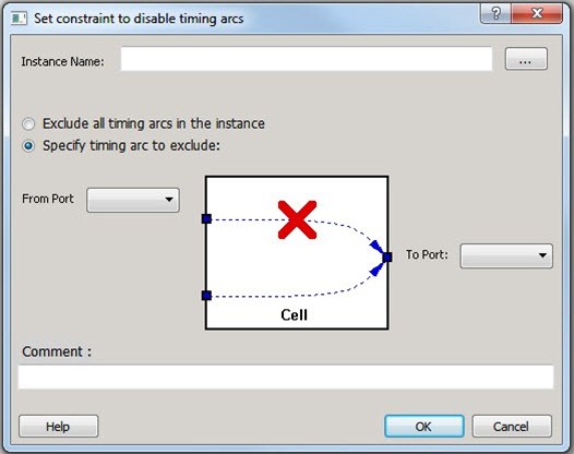
The following table describes the Set Constraint to Disable Timing Arcs dialog box options.
| Option | Description |
|---|---|
| Instance Name |
Specifies the instance name for which the disable timing arc constraint will be created. Click Browse next to the Instance Name box to open the Select instance to constrain dialog box. The following options are available on the Select instance
to constrain dialog box:
|
| Exclude All Timing Arcs in the Instance | Enables you to exclude all timing arcs in the specified instance. |
| Specify Timing Arc to Exclude | Enables you to specify the timing arc to exclude. In this case, you need to specify the from and to ports. |
| From Port | Specifies the starting point for the timing arc. |
| To Port | Specifies the ending point for the timing arc. |
| Comment | Enter a one-line comment for the constraint. |
12.5.1.1 Specifying Disable Timing Constraint
(Ask a Question)Use disable timing constraint to specify the timing arcs being disabled.
To specify the disable timing constraint:
- Add the constraint in the Editable
Constraints Grid or open the Set Constraint to Disable
Timing Arcs dialog box using one of the following methods:
- From the Constraints menu, click Disable Timing.
- Click the icon in the Constraints Editor.

- In the Constraints Editor, right-click Disable Timing and click Add Disable Timing Constraints.
- Select an instance from your design.
- Select whether you want to exclude all timing arcs in the instance or if you want to specify the timing arc to exclude. If you select Specify timing arc to exclude, select a from and to port for the timing arc.
- Enter any comments to be attached to the constraint.
- Click OK. The new
constraint appears in the constraints list.Note: When you click Save from the File menu, the newly created constraint is saved in the database.
12.5.2 Set Clock Source Latency Constraint
(Ask a Question)Use the clock source latency constraint to specify the delay from the clock generation point to the clock definition point in the design.
Clock source latency defines the delay between an external clock source and the definition pin of a clock.
You can specify both an "early" delay and a "late" delay for this latency, providing an uncertainty that the timing analyzer can use for propagating through its calculations. Rising and falling edges of the same clock can have different latencies. If only one clock source latency value is provided, the value is taken as the exact latency value for both rising and falling edges.
To specify a Clock Source Latency constraint, open the Set Clock Source Latency Constraint dialog box in one of the following four ways:
- In the Constraints Browser, double-click Clock Source Latency.
- Click the Clock Source Latency
Constraint
icon.

- From the Constraints menu, click Clock Source Latency .
- Right-click any row of Clock Latency Constraints Table and click Add Clock Source Latency. The Set Clock Source Latency Constraint dialog box appears.
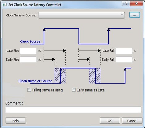
The following table describes the Set Clock Source Latency Constraint dialog box options.
| Option | Description |
|---|---|
| Clock Name or Source | To select the clock source, click the Browse
button to open the Choose the Clock Source Pin
dialog box. The only choice available for Pin Type is Clock Pins. |
| Late Rise | Specifies the largest possible latency (in nanoseconds) of the rising clock edge at the clock port or pin selected with respect to its source. Negative values are acceptable, but may lead to overly optimistic analysis. |
| Late Fall | Specifies the largest possible latency (in nanoseconds) of the falling clock edge at the clock port or pin selected with respect to its source. Negative values are acceptable, but may lead to overly optimistic analysis. |
| Early Rise | Specifies the smallest possible latency (in nanoseconds) of the rising clock edge at the clock port or pin selected with respect to its source. Negative values are acceptable, but may lead to overly optimistic analysis. |
| Early Fall | Specifies the smallest possible latency (in nanoseconds) of the falling clock edge at the clock port or pin selected with respect to its source. Negative values are acceptable, but may lead to overly optimistic analysis. |
| Falling same as rising | Specifies that the rising and falling clock edges have the same latency. |
| Early same as Late |
Specifies that the clock source latency must be considered a single value, not a range from early to late. |
| Comment | Enter a one-line comment to describe the clock source latency. |
12.5.3 Set a Clock Uncertainty Constraint
(Ask a Question)Use the Set Clock Uncertainty Constraint dialog box to set either the Simple Clock Uncertainty constraint or the Clock To Clock Uncertainty constraint from the Type drop-down menu. The default is Simple Clock Uncertainty.
12.5.3.1 Set Simple Clock Uncertainty Constraint
(Ask a Question)To open the Set Clock Uncertainty Constraint dialog box from the Constraints menu, choose Clock Uncertainty and select Simple Clock Uncertainty from the Type drop-down menu in Set Clock Uncertainty Constraint dialog box.

The following table describes the Set Clock Uncertainty Constraint dialog box options.
| Option | Description |
|---|---|
| Type |
Select Simple Clock Uncertainty (default) to set clock uncertainty constraint on a single clock. |
| Source |
Specifies the clock name as the uncertainty source. To set the source clock, click the Browse button to open the Select Source for Simple Uncertainty Constraint dialog box. The following options are available in the Select Source
for Simple Uncertainty Constraint dialog box:
|
| Uncertainity | Enter the time in ns that represents the amount of
deviation between two clock edges. |
| Use uncertainty for | Enables you to select whether the uncertainty constraint applies to setup, hold, or all checks. |
| Comment | Enables you to save a single line of text that describes this constraint. |
12.5.3.2 Set Clock-to-Clock Uncertainty Constraint
(Ask a Question)To open the Set Clock-to-clock Uncertainty Constraint dialog box from the Constraints menu, choose Clock Uncertainty, and select Clock To Clock Uncertainty from the Type drop-down menu.

The following table describes the Set Clock-to-clock Uncertainty Constraint dialog box options.
| Option | Description |
|---|---|
| Type | Select Clock To Clock Uncertainty. |
| From Clock | Specifies clock name as the uncertainty source. To set the From Clock, click the Browse button to open the Select Source Clock List for Clock-to-clock Uncertainty dialog box. The following options
are available in the Select Source Clock List for
Clock-to-clock Uncertainty dialog box:
|
| Edge | Enables you to select if the clock-to-clock uncertainty applies to rising, falling, or both edges. |
| To Clock | Specifies clock name as the uncertainty destination. To set the To Clock, click the Browse button to open the Select Destination Clock List for Clock-to-clock Uncertainty Constraint dialog box. The
following options are available in the Select Destination
Clock List for Clock-to-clock Uncertainty Constraint
dialog box:
|
| Uncertainty | Enter the time in ns that represents the amount of
deviation between two clock edges. |
| Use Uncertainty For | Enables you to select whether the uncertainty constraint applies to setup, hold, or all checks. |
| Comment | Enables you to save a single line of text that describes this constraint. |
12.5.4 Set a Clock Group
(Ask a Question)To add or delete a clock group constraint, open the Add Clock Groups Constraint dialog box in one of the following ways:
- From the Constraints menu, click Clock Groups.
- In the Constraints Browser, double-click Clock Groups.
- Right-click any row of Clock Groups Constraints Table and click Add Clock Groups.

The following table describes the Add Clock Groups Constraints dialog box options.
| Option | Description |
|---|---|
| ClockGroupsName | Enter a name for the clock groups to be added. |
| Exclusive Flag | Choose one of the following three clock group attributes for the
clock group:
|
| Add Group | Click Add to open a dialog box to add clocks to a clock group. In the Available Pins list, click the clocks, and then click Add to move them to the Assigned Pins list. Click OK. |
| Delete Group | Delete the clocks from a clock group. Select the group of clocks to be deleted and click Delete Group. This will delete the clock group. |
12.5.5 Set External Delay Constraint
(Ask a Question)Use set external timing constraint to specify the external delay between user-specified From and To ports (outside of chip). The delay is considered during Timing Analysis for PLL external feedback delay calculation when the PLL output goes outside of the chip through the From pin, and re-enters the chip through the To pin, which then connects to the PLL feedback clock input pin.
To set an external delay constraint, right click any row of Set External Delay Constraints table, and then click Add/Edit Set External Delay. When the Add Set External Delay Constraint dialog box appears, complete the options, and then click OK.

| Option | Description |
|---|---|
| From | Specify the output port or click Browse to
display the Select From Port for Set External Delay dialog box.
Available options are:
To filter the output port based on a specified pattern, click Filter, select one output port from the filtered results, and click OK. |
| To | Specify the input port or click Browse to
display the Select To Port for Set External Delay dialog box.
Available options are:
To filter the input port based on a specified pattern, click Filter, select one input port from the filtered results, and click OK. |
| Delay type | Choose one of the following delay type attributes for the
external delay:
|
| External Delay | Specify the external delay in nanoseconds between the From and To ports. |
| Comment | Enter a one-line comment for this constraint. |