10.1 Tutorial 1 - 32-Bit Shift Register with Clock Enable
This tutorial describes how to enter a clock constraint for the 32-bit shift register on SmartFusion2 device.
To set up your project:
- Invoke Libero SoC. From the Project menu, choose New Project.
- Type sf2_shift32 for your new project name and browse to a folder for your project location.
- Select Verilog as the Preferred HDL Type.
-
Leave all other settings at their default values.
Figure 10-2. New Project Creation - 32 Bit Shift Register 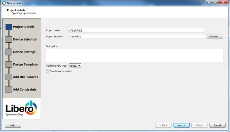
-
Click Next to go to Device Selection page. Make the
following selection from the pull-down menus:
- Family: SmartFusion2
- Die: M2S090TS
- Package: 484 FBGA
- Speed: STD
- Core Voltage: 1.2 V
- Range: COM
Figure 10-3. Selections from Pull-down Menus 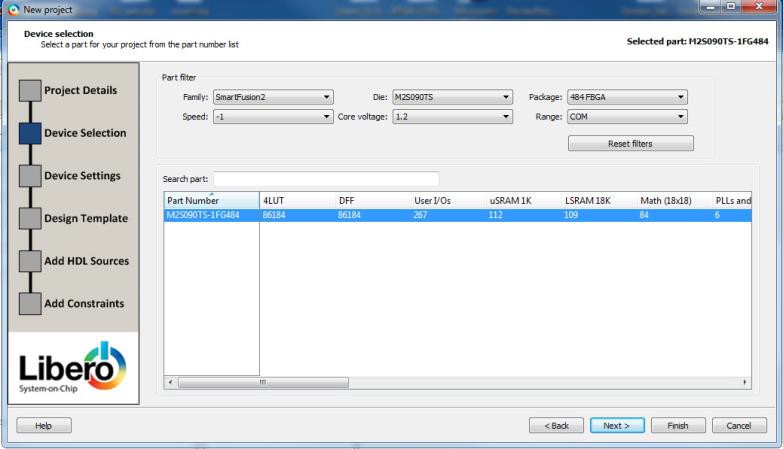
- Click the M2S090TS-1FG484 part number and click .
- Accept the default settings in the Device Settings page and click Next.
- Accept the default settings in the Design Template page and click Next.
- Click Next to go to the Add Constraints page.
- Since you are not adding any constraints, click Finish to exit the New Project Creation wizard.
-
To add a new HDL file, select File> New> HDL.
The Create a new HDL file dialog box appears.
-
Name the HDL file shift_reg32 as shown below and click
OK.
Figure 10-4. Create a New HDL File Dialog Box 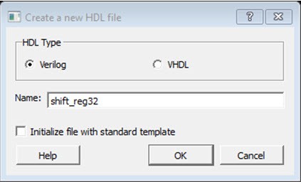
-
Copy the following code and paste it into the Verilog file:
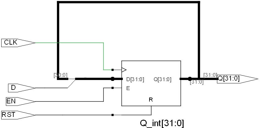
                            module shift32 ( Q,CLK,D,EN,RESET); input
                                D,EN,CLK,RESET;
                            output[31:0] Q; reg [31:0] Q_int;
                            assign Q=Q_int;
                            always@ (posedge CLK) begin
                            if(RESET)
                            Q_int<=0; else begin if(EN)
                            Q_int<={Q_int[30:0],D}; end
                            end endmodule
- Check the HDL file to confirm there are no syntax errors.
-
Confirm that the shift_reg32 design appears in the Design Hierarchy window, as
shown in the following figure.
Figure 10-5. shift_reg32 in the Design Hierarchy Window 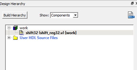
-
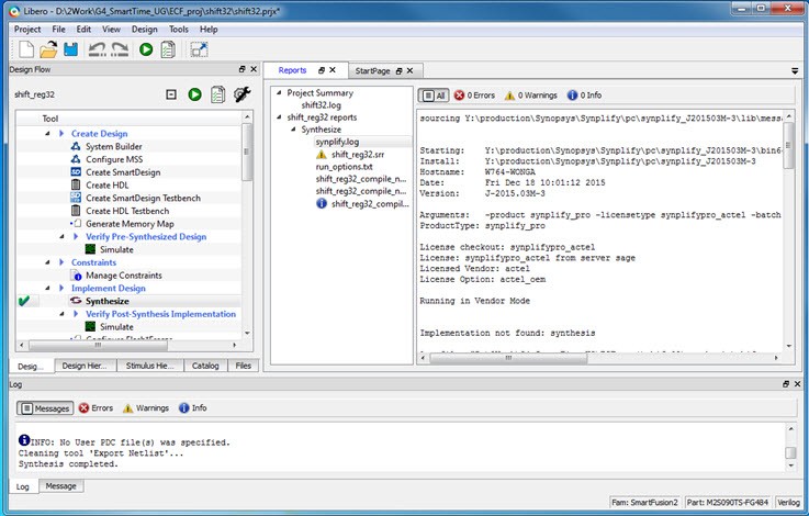
In the Design Flow window, double-click Synthesize to
run Synplify Pro with default settings.
A green check mark appears next to Synthesize when Synthesis is successful, as shown in the following figure.
Figure 10-6. Synthesis and Compile Complete - 32-Bit Shift Register with Clock Enable