10.1.3 Maximum Delay Analysis with Timing Analyzer - 32-Bit Shift Register Example
The SmartTime Maximum Delay Analysis window shows the design maximum operating frequency along with any setup violations.
-
Right-click Open SmartTime in the Design Flow window
and choose Open Interactively to open SmartTime. The Maximum Delay
analysis window appears. A green check next to the clock name indicates there
are no timing violations for that clock domain. The Summary page displays a
summary of the clock domain timing performance.
The Maximum Delay Analysis Summary appears with the following information shown:
- Maximum operating frequency for the design
- External setup and hold requirements
- Maximum and minimum clock-to-out times. In this example, the maximum clock frequency for CLK is 609.75 MHz.
Figure 10-14. Maximum Delay Analysis - Summary 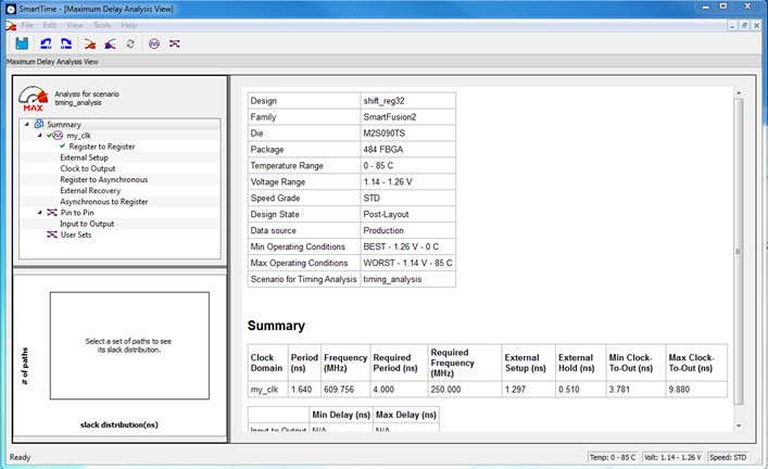
-
Expand my_clk to display the Register to Register,
External Setup, and Clock to Output path sets.
Figure 10-15. SmartTime Register-to-Register Delay 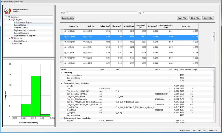
-
Select Register to Register to display the
register-to-register paths.
The window displays a list of register- to-register paths and detailed timing analysis for the selected path. All the slack values are positive, indicating that there are no setup time violations
-
Double-click a path row to open the Expanded Path window.
The window shows a calculation of the data arrival and required times, along with a schematic of the path.Note: Timing numbers in the reports may vary slightly with different versions of the Libero software, and may not be what you see when you run the tutorial.
Figure 10-16. Register-to-Register Expanded Path View 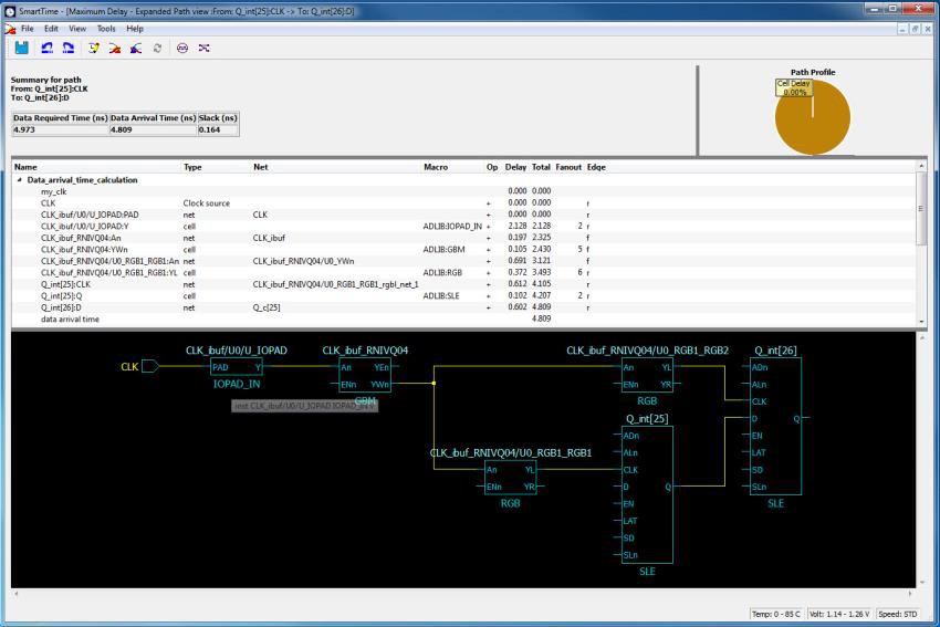
- Select External Setup to display the Input to Register timing.
-
Select Path 3.
The Input Arrival time from the EN pin to Q_int[27]:EN is 4.547 ns.
Figure 10-17. SmartTime - Input to Register Path Analysis 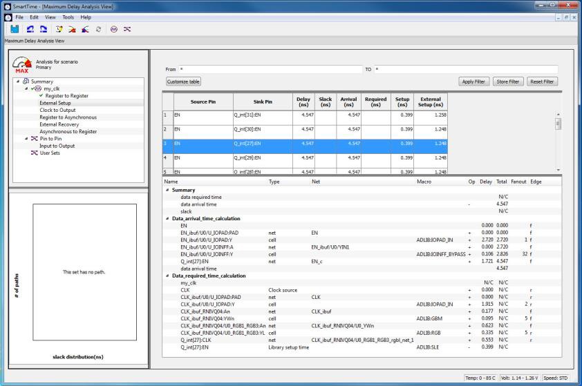
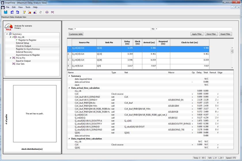
- Select Clock to Output to display the register to output timing.
-
Select Path 1.
The maximum clock to output time from Q_int[16]:CLK to Q[16 ] is 9.486 ns.
Figure 10-18. SmartTime Clock to Output Path Analysis