
1.4.1 Main Crystal Oscillator
(Ask a Question)The main crystal oscillator works with an external crystal, ceramic resonator, or a resistor-capacitor network to generate a high-precision clock in the range of 32 kHz to 20 MHz and is connected via the pins XTLOSC_[MAIN/AUX]_EXTAL and XTLOSC_[MAIN/AUX]_XTAL.
The following table lists the output frequency range of the main crystal oscillator with different possible sources.
Source | Output Frequency Range |
|---|---|
Crystal | 32 kHz to 20 MHz |
Ceramic Resonator | 500 kHz to 4 MHz |
R C Circuit | 32 kHz to 4 MHz |
The main crystal oscillator is operated in medium gain mode when a ceramic resonator is connected between the XTLOSC_[MAIN/AUX]_EXTAL and XTLOSC_[MAIN/AUX]_XTAL pins.
When a crystal is used, the load capacitance is determined by the external capacitors C1 and C2, internal capacitance, and stray capacitance (CS), as shown in the following figure.
The oscillator and the load capacitance should be used as per the recommendation of the manufacturer.
|
CRYSTAL 32.768 kHz 12.5 pF SMD | Citizen | CM519-32.768KEZF-UT |
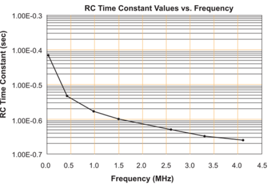
The frequency generated by an RC network is determined by the RC time constant of the selected components, as shown in the following figure.
The R and C components are connected to the XTLOSC_[MAIN/AUX]_EXTAL pin, with the XTLOSC_[MAIN/AUX]_XTAL pin connected to the power pin VPP, as shown in the following figure.
The operating mode of the main crystal oscillator is configured by the oscillator's macro available in Libero SoC.