
3.14 Bluetooth® Low Energy Throughput
- Connection with mobile phone via BLE.
- Data transmission from the Curiosity board to smart phone via BLE and throughput evaluation.
- Data transmission from smart phone to the Curiosity board via BLE and throughput evaluation.
Data Format for Advertising
Advertising Data:
The Service Data type is used in advertising data. The data format is as illustrated below:
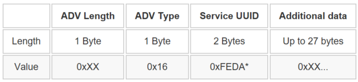
0xFEDA is a 16-bit Service UUID which is purchased by
Microchip from Bluetooth SIG.Scan Response Data: The device name is placed in the scan response. the device name is set as “BLE_UART_XXXX”. (XXXX are the last two bytes of the device address.)
Supported Services and Profiles: The supported service and profile are listed in the following section.
- Transparent Service: MCHP proprietary service. For more details, refer to Microchip Transparent Service v1.1.
- Device Information Service: Bluetooth SIG standard service. For more details, refer to Specifications.
Profiles:
- Transparent Profile (TRP): MCHP proprietary profile. For more details, refer to Microchip Transparent Profile v1.1.
- Advertising State (No LE link existed): Green LED flashes one time every 500 ms.
- Connected with peer device: Green LED is solid ON.
Interaction with MBD App
Interaction with MBD App: Working with iOS MBD App
Scanning and Connecting the Device: The steps to scan and connect to the device via MBD app are described as follows:
-
Tap “BLE UART” feature in MBD App
Figure 3-161. MBD App iOS Version 
-
Tap on the PIC32CXBZ.
Figure 3-162. BLE UART GUI 
- Tap on START
Figure 3-163. PIC32CXBZ GUI 
-
Select BLE_UART_XXXX (XXXX are the last two bytes of the device address)
Figure 3-164. “START” Scanning GUI 
Firmware Version
-
To verify firmware version, once LE is connected, tap the Setting Icon:
Figure 3-165. Settings Icon 
- The firmware version detail will
be listed along with other Device Information as illustrated in the following
figure.
Figure 3-166. Firmware Revision in "Setting" GUI 
Select Transparent Profile
- Legacy Transparent Profile (TRP): Supported by “BLE_THROUGHPUT” firmware.
- Transparent Credit Based Profile (TRCBP): Not supported by “BLE_THROUGHPUT” firmware.
Select GATT Write Type
TRP profile supports both “Write with Response” and “Write without Response”, which is much higher than the former.

Demo Modes
- Burst Mode: is designed for the throughput evaluation via massive data transmission.
- Text Mode: is designed for the simple text typing.

-
Burst Mode
There are four data transfer modes supported in the Burst mode:
- Check sum Mode: MBD App to the device (uni-direction).
- Fixed Pattern Mode: Device to MBD App (uni-direction).
- Loop back Mode: MBD App → Device → MBD App (bi-direction).
- UART Mode:
MBD App → Device → UART output to PC. UART input from PC → Device → MBD App (bi-direction). This mode is not supported by “BLE THROUGHPUT” firmware.
Figure 3-169. BLE UART Mode in “Setting” GUI 
-
Text Mode
There are two data transfer modes supported in the Text mode:- Loop back Mode: MBD App → Device → MBD App (bi-direction).
- UART Mode: MBD App → Device → UART output. This mode is not supported by “BLE THROUGHPUT” firmware.
Figure 3-170. Text Mode “Setting” GUI 
Working with Android MBD App
The operation of Android MBD App is quite similar as the iOS version MBD App.
Throughput Evaluation
This section describes the Throughput Evaluation steps and provides a list of throughput figures tested with various phone models (for reference only). Additionally, it examines the factors influencing throughput.
Hardware Requirement
| Tool | Qty |
|---|---|
|
Curiosity board | 1 |
|
Micro USB cable | 1 |
|
Android/iOS Smartphone | 1 |
Software Requirement
- MPLAB X IPE: For programming the precompiled hex file.
- MPLAB X IDE: For programming the application example.
- Teraterm: Terminal Emulator for displaying UART output.
Smart Phone App
- Microchip Bluetooth Data (MBD)
Programming the Precompiled Hex File or Application Example
Programming the .hex File using MPLAB X IPE
- Import and program the
precompiled
.hexfile located in “<Harmony Content Path>\wireless_apps_ble\apps\ble_throughput\hex” folder - For more information on the
programming steps, refer to the Programming a Device in MPLAB IPE.Note: Users must choose the correct device and tool information.
Programming the Application using MPLAB X IDE
- Follow the steps mentioned in Running a Precompiled Example
- Open and program the application
example “
ble_throughput_xxxx.X” where xxxx refer to device (for example: WBZ451, project file:ble_throughput_wbz451.X) located in “<Harmony Content Path>\wireless_apps_ble\apps\ble_throughput\firmware" using MPLAB X IDE
For more details on finding the Harmony content path, refer to Installing the MCC Plugin.
Demo Description
- Refer BLE Throughput Demo Description. Note: The BLE connection status will be indicated by the green color of the RGB LED.
Developing the Application from Scratch using MCC
- Create a new MCC Harmony Project by selecting the device. For more details, refer to Creating a New MCC Harmony Project.
- Launch the MPLAB Code
Configurator from the toolbar as illustrated below. The project graph will open
with the default components.
Figure 3-171. MCC 
- In the Device Resources window,
expand Libraries > Harmony > Wireless > Application
Services. Then, click the Plus Symbol to add the BLE
Config App Service Component to the project
Figure 3-172. BLE Config App Service 
- All BLE Stack related components will be added into the project graph. Accept dependencies or satisfiers by selecting Yes.
- For configuring BLE Config App Service component based on the device refer to Adding BLE Config App Service Component to Project Graph and Selecting the Device in Getting Started with WME Bluetooth Low Energy Applications from Related Links.
- Add and verify Transparent App
Service Component configuration as illustrated in the following figure:
Figure 3-173. Transparent App Service 
- To enable digital and communication interfaces, refer to Enabling Digital Input/Output and Communication Interfaces Through System Hardware Definition (SHD) component in Getting Started with WME Bluetooth Low Energy Applications from Related Links.
- For FreeRTOS component
settings refer to the Configuring FreeRTOS in Getting Started with WME
Bluetooth Low Energy Applications from Related Links. Additionally,
change FreeRTOS Component settings as illustrated in the following
figure.
Figure 3-174. FreeRTOS Configuration 
- For WBZ451
- Change
WBZ451-CURIOSITY Component setting as illustrated in the
following figure
Figure 3-175. WBZ451-CURIOSITY Configuration 
- Verify if the project
graph window has all the expected components. as illustrated in the
following figure:
Figure 3-176. Project Graph 
- Change
WBZ451-CURIOSITY Component setting as illustrated in the
following figure
- For WBZ451
- Change
WBZ351-CURIOSITY Component setting as illustrated in the
following figure image
Figure 3-177. WBZ351-CURIOSITY Configuration 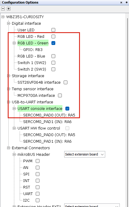
- Change SERCOM0
Component setting as illustrated in the following figure
Figure 3-178. SERCOM0 Configuration 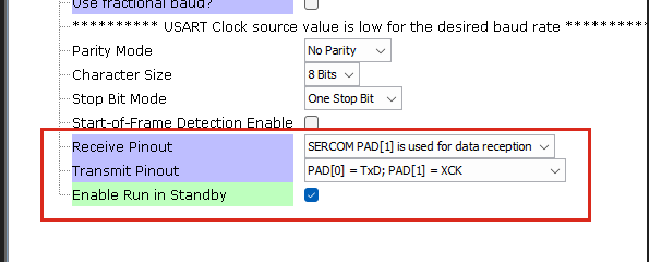
- Verify if the project
graph window has all the expected components as illustrated in the
following figure:
Figure 3-179. Project Graph 
- Change
WBZ351-CURIOSITY Component setting as illustrated in the
following figure image
- Change BLE Stack component
configuration as illustrated in the following figure:
Figure 3-180. BLE Stack Configuration 
Figure 3-181. BLE Stack Configuration 
- Add and verify Device
Information Service Component configuration as illustrated in the
following figure:
Figure 3-182. Device Information Service Configuration 
Generating a Code
For more details on code generation, refer to the MPLAB Code Configurator (MCC) Code Generation.
Files Containing User Application Code

| Source Files | Usage |
|---|---|
app.c | Application State machine, includes calls for Initialization of all BLE stack (GAP,GATT, SMP, L2CAP) related component configurations |
app_ble_callbacks.c | All the event functions related to GAP, GATT, SMP and L2CAP events that user can use or modify . |
app_trsps_callbacks.c | All the event functions related to
trspc event handles that user can use or
modify. |
app_utility.c | Contains generic utility functions that serve the purpose of providing reusable, common functionalities that can be applied across various parts of a program. |
app.c is auto generated and has a
state machine based application code sample. Users can use this template to develop
their application. Main application logic is implemented in void
APP_Tasks() function.app.c
app.c
The BLE Throughput Example Firmware Diagram

References
- Bluetooth Low Energy Throughput Application for: WBZ451
- Bluetooth Low Energy Throughput Application for: WBZ351
- Microchip Transparent Service_v1.1
- Microchip Transparent Profile_v1.1
- www.bluetooth.com/specifications/gatt/
- developer.apple.com/accessories/Accessory-Design-Guidelines.pdf
- www.bluetooth.com/specifications/specs/core-specification-5-3/