
3.16 Bluetooth® Low Energy Proximity Reporter
The Proximity Reporter application provides comprehensive guidance on setting up, programming, and testing a BLE Proximity Reporter using the Curiosity board. This section details the necessary hardware and software requirements, the Bluetooth Low Energy proximity profile, and specific services involved. It also includes step-by-step instructions and test scenarios for implementing and validating the application.
Recommended Reading
- BLE Software Specification
- Getting Started with WME Bluetooth Low Energy Applications
Hardware Requirement
| Tool | Quantity |
|---|---|
| Curiosity Board | 1 |
| Micro USB Cable | 1 |
| Mobile | 1 (Smart phone with the Microchip Bluetooth Data (MBD) app installed) |
Software Requirements
- MPLAB X IPE: For programming the precompiled hex file.
- MPLAB X IDE: For programming the application example.
Programming the Precompiled Hex File or Application Example
Programming the .hex File using MPLAB X IPE
- Precompiled
.hexfile is located in “<Harmony Content Path>\wireless_apps_ble \apps\ble_pxpr_app\hex” folder. - For more information on the
programming steps, refer to the Programming a Device in MPLAB IPE.Note: Users must choose the correct device and tool information.
Programming the Application using MPLAB X IDE
- Follow the steps mentioned in Running a Precompiled Example
- Open and program the application
example “
ble_pxpr_app_xxxx.X” where xxxx refer to device (for example: WBZ451, project file:ble_pxpr_app_wbz451.X) located in “<Harmony Content Path>\wireless_apps_ble\apps\ble_pxpr_app\firmware” using MPLAB X IDE
For more details on finding the Harmony content path, refer to Installing the MCC Plugin.
Demo Description
- Refer to PXPR Demo Description.
Developing the Application from Scratch using MCC
- Create a new MCC Harmony Project by selecting the device. For more details, refer to Creating a New MCC Harmony Project.
- Launch the MPLAB Code
Configurator from the toolbar as illustrated below. The project graph will open
with the default components.
Figure 3-202. MCC 
- In the Device Resources window,
expand Libraries > Harmony > Wireless > Application
Services. Then, click the Plus Symbol to add the Proximity
App Service Component to the project graph.
Figure 3-203. Proximity App Service 
- All BLE PXPR related components will be added into the project graph. Accept dependencies or satisfiers by selecting Yes
- For configuring BLE Config App Service component based on the device refer to Adding BLE Config App Service Component to Project Graph and Selecting the Device in Getting Started with WME Bluetooth Low Energy Applications from Related Links.
- To enable digital and communication interfaces, refer to Enabling Digital Input/Output and Communication Interfaces Through System Hardware Definition (SHD) component in Getting Started with WME Bluetooth Low Energy Applications from Related Links.
- Change FreeRTOS component
settings as illustrated in the following figure. For more details, refer to the
Configuring FreeRTOS in Getting Started with WME Bluetooth Low
Energy Applications from Related Links.
Figure 3-204. FreeRTOS Configuration 
-
Select the Proximity App Service component. In the Configuration Options, select the Enable Reporter Role. Additionally, ensure that the Enable Immediate Alert Service , Enable TX Power Service and Enable app code generation option is enabled.
Figure 3-205. Proximity App Service 
Figure 3-206. Proximity App Service Configuration 
- For WBZ451
- Change
WBZ451-CURIOSITY Component setting as illustrated in the
following figure image
Figure 3-207. WBZ451-CURIOSITY Configuration 
- Verify if the project
graph window has all the expected components, as illustrated in the
following figure:
Figure 3-208. Project Graph 
- Change
WBZ451-CURIOSITY Component setting as illustrated in the
following figure image
- For WBZ351
- Change
WBZ351-CURIOSITY Component setting as illustrated in the
following figure image.
Figure 3-209. WBZ351-CURIOSITY Configuration 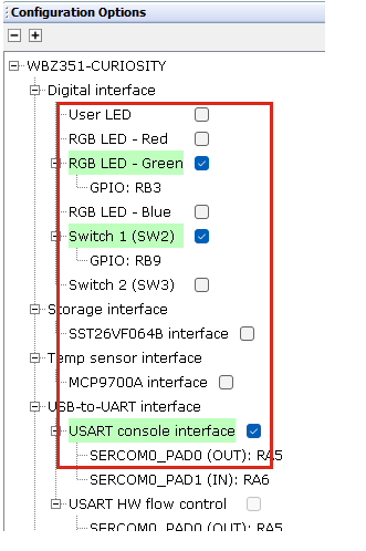
- Verify if the project
graph window has all the expected components, as illustrated in the
following figure:
Figure 3-210. Project Graph 
- Change
WBZ351-CURIOSITY Component setting as illustrated in the
following figure image.
- Enabling the Enable Reporter
Role option in Proximity App Service component will configure
BLE Stack component . Additionally, selecting the Enable App Code
Generation option will generate the necessary application files related
to the service during the code generation process. Verify the BLE Stack configuration.
Figure 3-211. BLE Stack Configuration 
Figure 3-212. BLE Stack Configuration 
Generating a Code
For more details on code generation, refer to the MPLAB Code Configurator (MCC) Code Generation.
Files Containing User Application Code

| Source Files | Usage |
|---|---|
app.c | Application State machine, includes calls for Initialization of all BLE stack (GAP,GATT, SMP, L2CAP) related component configurations |
app_ble_callbacks.c | All the event functions related to GAP, GATT, SMP and L2CAP events that user can use or modify . |
app_pxpr_callbacks.c | All the event functions related to PXPR event handles that user can use or modify. |
app_utility.c | Contains generic utility functions that serve the purpose of providing reusable, common functionalities that can be applied across various parts of a program. |
app.c is auto generated and has
a state machine based application code sample. Users can use this template to
develop their application. Main application logic is implemented in void
APP_Tasks() functionapp.c
app.c
Proximity Profile
In the context of Bluetooth Low Energy, “proximity” generally refers to the physical closeness between two BLE devices. The BLE Proximity profile is a standardized BLE profile that enables a device to alert a user when another device is near or far away from it.
The Proximity profile defines the behavior when a device moves away from a peer device so that the connection is dropped or the path loss increases above a preset level, causing an immediate alert. This alert can be used to notify the user that the devices has disconnected.
- Proximity Reporter (Server)::This refers to the tracked device, which could be an item like a key fob or any other asset whose proximity is to be monitored
- Proximity Monitor (Client): This device monitors the reporter's proximity, typically through a smart phone or tablet
The Proximity profile uses the RSSI (Received Signal Strength Indicator) to determine the approximate distance between the Monitor and the Reporter.
Role/Service Relationships

Proximity Reporter Requirements
The Proximity Reporter must have one instance of the Link Loss Service and may have instances of both the Immediate Alert Service and the Tx Power Service. these services are described in detail below:
Link Loss Service
Link loss service in Bluetooth Low Energy is a standard service defined by the Bluetooth Special Interest Group (SIG) to alert a device when it loses connection with another device.
- The Link Loss Service uses the Alert Level characteristic to cause an alert in the device when the link is lost.
- The Link Loss Service can be
instantiated as a “Primary Service”. The service UUID can be set to the UUID
value assigned to “Link Loss” which is
0x1803.
Service Characteristics: The Alert Level Characteristic is used to expose the current link loss alert level that is used to determine how the device alerts when the link is lost.
|
Characteristic |
Mandatory/Optional |
Characteristics Property |
|---|---|---|
|
Alert Level |
Mandatory |
Read, Write |
Characteristic Behavior: The Alert Level characteristic can be set to “No Alert,” “Mild Alert,” “High Alert”.
Service Behaviors
- No Alert: alter will be disabled
- Mild Alert: triggers the mild alert
- High Alert: this will trigger the strongest possible alert
The specific action that occurs in the device for the mild and high alerts is implementation specific. For example, this could include flashing lights, making noises, moving, or other methods to alert the user.
- An implementation-specific timeout
- User interaction on this device
- The physical link is reconnected
Immediate Alert Service: This service exposes a control point to allow a peer device to cause the device to alert immediately. The proximity monitor will calculate the path loss:
Path Loss: Tx Power Level - RSSI
If the path loss exceeds a certain threshold, the monitor can write the alert level characteristic of the IAS, thereby prompting the user to perform appropriate action to avoid disconnection.
The alert level characteristic can be written using the GATT Write without Response sub-procedure with an alert level of “No Alert,” “Mild Alert,” “High Alert,” to set the written alert level.
| Characteristic | Mandatory/Optional | Characteristics Property |
|---|---|---|
| Alert Level | Mandatory | Write, Without Response |
- No Alert: alter will be disabled
- Mild Alert: triggers the mild alert
- High Alert: this will trigger the strongest possible alert
The specific action that occurs in the device for the mild and high alerts is implementation specific. For example, this could include flashing lights, making noises, moving, or other methods to alert the user.
TX Power Service
The TX Power Service uses the TX power level characteristic to expose the current transmit power level of a device when in a connection.
| Characteristic | Mandatory/Optional | Characteristics Property |
|---|---|---|
| TX Power Level | Mandatory | Read |
The TX Power Level characteristic returns the current transmit power level when read using the GATT Characteristic Read.
Proximity Reporter Application
In this section, the focus is on the Proximity Reporter application implementation specific details. In terms of the application design and testing methods.
Working Flow
APP_PXPR_STATE_IDLE: application remains in the Idle mode.APP_PXPR_STATE_ADV: application is waiting for a connection without bond within timeout_adv seconds duration.APP_PXPR_STATE_BOND_ADV: application is waiting for a reconnection with bond within timeout_with_bond_adv seconds duration.APP_PXPR_STATE_CONN: application is prepared to respond to Proximity Monitor role.

Input and Output Interface
Input
The application relies on Button 1 as the input.
- Types of Pressing:
- Press: Press the button for less than 500 ms.
- Long press: Press the button for more than 500 ms.
- Application behavior on button press in different state co relation.
|
State |
Action |
Behavior |
|---|---|---|
|
|
Long press Button 1 |
Disconnect the existing connection, enable advertisement and allow new device to be bonded |
|
|
Long press Button 1 |
Enable advertisement and allow new device to be bonded |
Output
- Current application state: The RGB LED (blue) is used
- Alert state: User LED (blue) is used
|
APP Connection State |
LED Behavior |
|---|---|
APP_PXPR_STATE_IDLE |
All LEDs are turned OFF. |
APP_PXPR_STATE_ADV |
The RGB LED (blue) flashes once every 3 seconds. (ON: 50 ms, OFF: 2950 ms) |
APP_PXPR_STATE_BOND_ADV |
The RGB LED (blue) flashes twice every 3 seconds. (ON: 50 ms, OFF: 50 ms) |
APP_PXPR_STATE_CONN |
The RGB LED (blue) flashes twice every 1.5 seconds. (ON: 50 ms, OFF: 150 ms) |
The User LED pattern indicates the alert state according to the following table:
|
APP Alert Level |
LED Behavior |
|---|---|
|
|
User LED (Blue) remains ON |
|
|
User LED (Blue) blinks once every second |
|
|
User LED (Blue) blinks five times every second |