4.3.5.2.2 Plug and Play with the Curiosity Nano
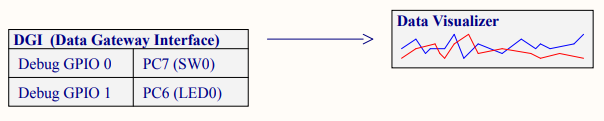
The AVR128DA48 Curiosity Nano Evaluation board is designed to be plug-and-play. Therefore plug the board into the PC using the USB cable and then launch MPLAB X IDE. When the IDE opens, you should see a Kit Window tab with information about the Curiosity Nano. Click on the board schematics link and on the first page of the schematics find GPIO pin references that can be used with the MPLAB Data Visualizer. PC7 is attached to the board pushbutton switch and PC6 is attached to LED0.
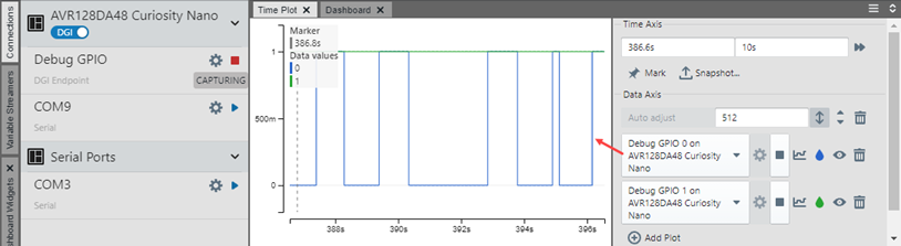
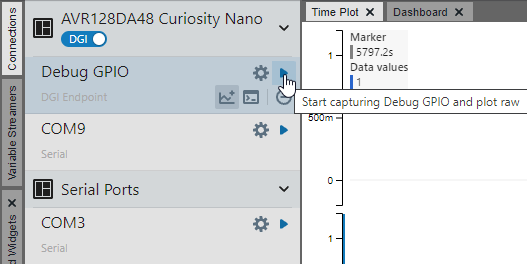
Open the MPLAB Data Visualizer plugin. The visualizer will display available data sources, including Debug GPIO for the GPIO pins. Click on the arrow to plot all pins.
On the Graph, both GPIO pin outputs are plotted on a single axis. On the right side of the graph you will see information about each plot, including its color-coding.
Now it’s time to play with the Curiosity Nano. Press the board switch to see a pulse on GPIO 0. Note that there is lag between when the button is pressed and when the pulse appears. Refer again to the schematic to see that there is no pull-up on the button. However, pin pull-ups can be enabled using software. Also, GPIO 1 is only showing a single-line plot, but a pulse produced from a timer could provide a more interesting plot. Therefore it is time to create a project and add some code.