
4.9 Dynamic Configuration of CCC
(Ask a Question)Each CCC has a dynamic reconfiguration interface (DRI), which can be enabled to configure CCC parameters without reprogramming the device. The CCC configuration is controlled by volatile configuration registers that are loaded with values from the flash configuration bits at power-up. An APB bus master must be interfaced to the CCC using a DRI macro for dynamic configuration. The APB bus master is used to dynamically modify the CCC configuration register values as per design needs. For more information on CCC configuration registers and their bit definitions, see PolarFire Device Register Map or PolarFire SoC Register Map.
To meet all the datasheet specifications, there are certain requirements that must be met when configuring the PLL/DLL parameters. The Libero CCC configurator implements all these requirements and creates a valid solution for the requested output clock frequencies and phases. Therefore, it is recommended that users generate the required configuration using the Libero CCC configurator and use the generated parameters in their dynamic configuration solution.
The PLL_POWERDOWN_N input must be asserted before making changes to the PLL configuration parameters. Asserting the PLL_POWERDOWN_N signal resets the PLL operation.
When the CCC is configured in the internal Post-VCO feedback mode, if the requirement is to change the phase or output divider configuration then the clock start/stop (OUT#_EN) signals can be used to stop the clock output before making the changes for glitchless configuration.
The following steps describe how to perform dynamic configuration of a CCC:
- Select Enable Dynamic Reconfiguration Interface in the CCC configurator as shown in the following figure.
Figure 4-29. Clock Conditioning Circuitry Window 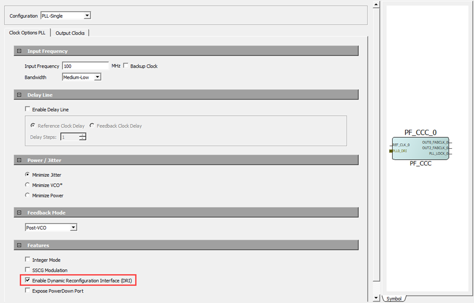
- Instantiate a Dynamic Reconfiguration Interface
macro into the SmartDesign. The dynamic reconfiguration interface macro converts the
APB interface signals to CCC dynamic reconfiguration interface signals.
The following table lists the ports for DRI. These ports are routed through hardwired connections to CCC. The DRI ports cannot be monitored or altered in the Libero design. These ports are used to facilitate HDL simulation of changes made to the CCC over the DRI. The DRI macro provided in the Libero Catalog takes care of converting standard APB3 read/writes to DRI transactions.
Table 4-9. DRI Port List Port Name Direction Description DRI_CLK Input Internal subsystem peripheral clock DRI_WDATA[32:0] Input Write data DRI_ARST_N Input Active low DRI asynchronous reset DRI_CTRL[10:0] Input Control bits DRI_RDATA[32:0] Output Read data DRI_INTERRUPT Output Interrupt signal - Double-click the Dynamic Reconfiguration Interface macro to configure.
- In the macro configurator, under the CCC
tab, select the PLLs and DLLs that need dynamic configuration. DRI macro interface
is shown in the following figure.
Figure 4-30. Dynamic Reconfiguration Interface Configurator 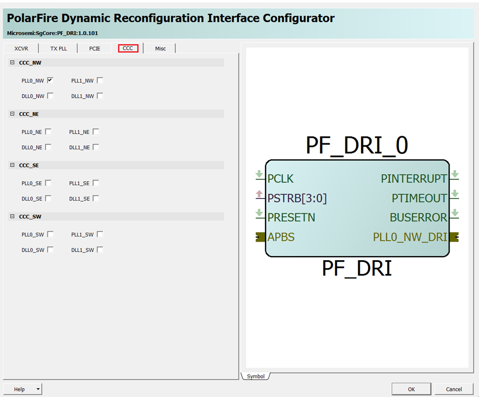
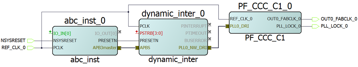
- Connect the APB master port from an APB master (for example, CoreABC) to the DRI macro’s mirrored master port. See the following figure for connections.
Now, the APB master can dynamically configure the CCC configuration registers. For more information about how to use the DRI interface, see AN4592: PolarFire FPGA Dynamic Reconfiguration Interface Application Note (earlier AC475).