
4.2 Setting Up Signal Channels
To edit signal channels, perform the following step:
In the Edit Signal Channel window, click Edit > Edit Signal Channel.
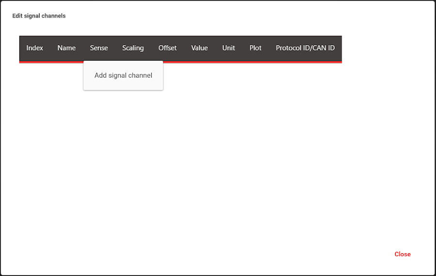
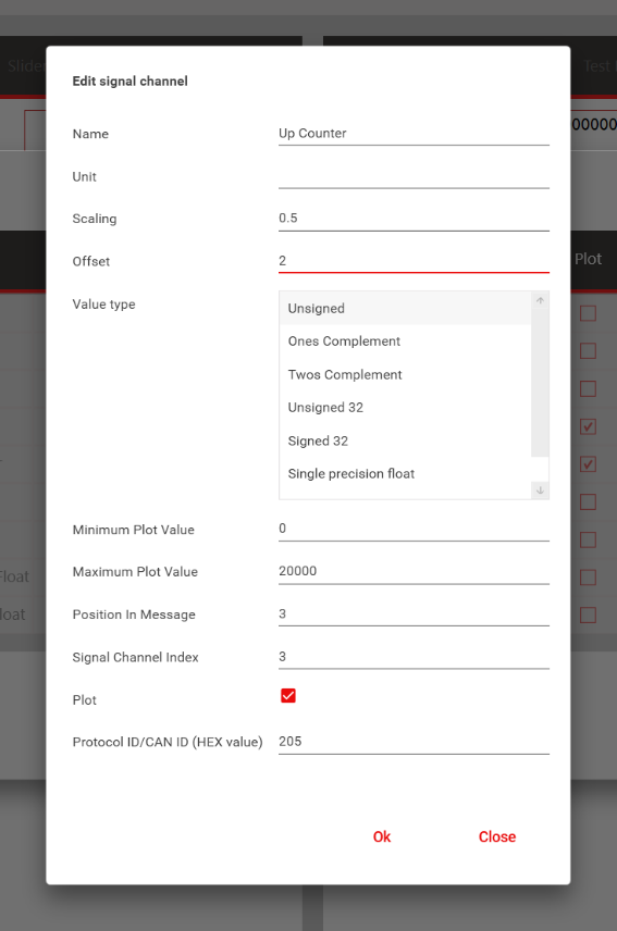
From the pop-up table, signal channels can be added, removed and edited with a right-click on the table header. The order in which the signal channels are added is not important, but it is good practice to add them in the order in which they are transmitted in the data stream package (position in message).
A signal definition requires the information shown in Table 4-1.
| Name | Description |
|---|---|
|
Name | Name of the signal |
|
Unit | Unit of the signal |
|
Scaling |
The scaling value is calculated using the following formula: scaled_value = raw_value * scaling +
offset A multiplier. The raw values can be scaled by this factor. In the example, the value received will be multiplied by 0.5. |
|
Offset | This adds an offset to the raw data. In the example, 2 will be added to the received value. |
| Value Type | Encoding of the data is sent from the embedded system. |
|
Minimum Plot Value | The minimum value plotted on the Monitoring tab. In the example, values greater or equal to 0 will be plotted. |
|
Maximum Plot Value | The maximum value plotted on the Monitoring tab. In the example, values less than or equal to 2000 will be plotted. |
|
Position in Message | The position of the 16-bit signal channel in the data frame. The first two bytes are position 0, the second two bytes are position 1, etc. |
|
Signal Channel Index | Each signal channel entry must have a unique identifier. Assign that number here. |
|
Plot | Check box to enable plotting on the Monitoring tab. |
|
Protocol ID/Can ID | Protocol ID or CAN ID of the corresponding frame in hexadecimal |
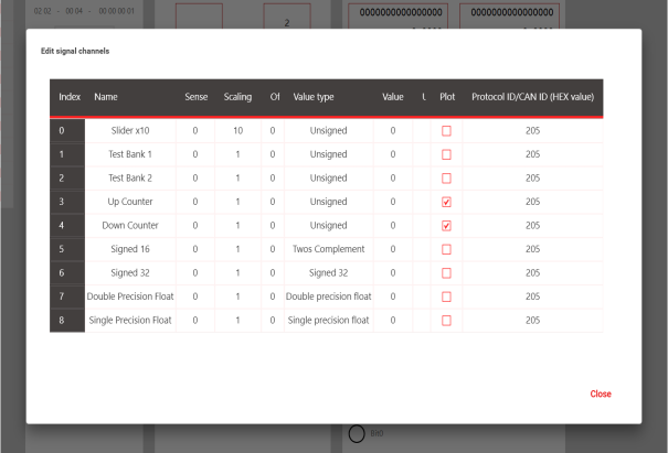
The following table lists the signal names and their positions.
| Index No | Signal Name | Type | Positions Occupied in Message |
|---|---|---|---|
| 0 | Slider x10 | Unsigned, 16-bit | 0 |
| 1 | Test Bank 1 | Unsigned, 16-bit | 1 |
| 2 | Test Bank 2 | Unsigned, 16-bit | 2 |
| 3 | Up Counter | Unsigned, 16-bit | 3 |
| 4 | Down Counter | Unsigned, 16-bit | 4 |
| 5 | Signed 16 | Twos Compliment, 16-bit | 5 |
| 6 | Signed 32 | Signed 32, 32-bit | 6, 7 |
| 7 | Double Precision Float | Double Precision Float, 64-bit | 8, 9, 10, 11 |
| 8 | Single Precision Float | Single Precision Float, 32-bit | 12,13 |