This video gives an overview of the Device Programming dialog box to check the kit
connection. The ATtiny817 Xplained Pro kit has an onboard embedded debugger (EDBG) which
eliminates the need for a dedicated programmer/debugger. This section will also go through
the process of associating the EDBG with your project.
Todo: Associate
the EDBG on your ATtiny817 Xplained Pro kit with your project.
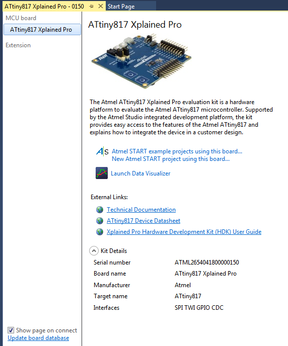
Connect the ATtiny817 Xplained Pro
board to the computer using the provided Micro-USB cable. The kit page should be
present in Microchip Studio, as in the figure below. Figure 2-10. ATtiny817 Xplained Pro
Start Page
There are links to
documentation for the board and data sheet for the device.
It is possible to create an
Atmel START project for the board. Clicking on the Atmel START project links
will bring you into Atmel START, where you get options for this specific
board.
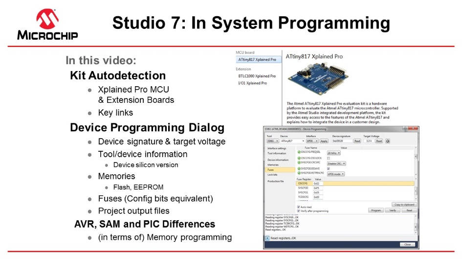
Opening the Programming Dialog
by Tools → Device Programming.
Select EDBG Tool and assure
that Device = ATtiny817, then you may read Device Signature and Target
Voltage.
Interface settings: You may
see and change the interface clock frequency.
Tool information: Shows
information about the EDBG tool.
Device information: Shows information about
the device. Note that you can also see the silicon revision of the device,
which may be helpful in customer support cases.
Memories: May program the Flash, EEPROM, and
user signature separately from the files.
Fuses: Read and set fuses, for instance,
oscillator frequency (16 or 20 MHz), brown-out voltage detection, etc.
Lock bits: Lock memory.
Production file: Program the device using a
production file to program Flash, EEPROM, and user signatures.
Note that AVR has Flash in the hex file and
EEPROM in the EEP files, while PIC has everything, even fuses, in a hex
file.
For instance, SAML21J devices don't have
EEPROM (can be emulated in Flash). It also has a security bit option to lock
the device.
Create a new project by selecting File
→ New project. Select, for instance, C executable project, select the device by
filtering on the device name. Another Getting Started video discusses different
project types.
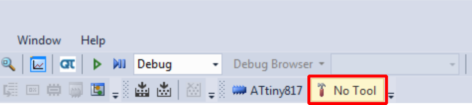
If a project is selected, click the
Tool button located in the top menu bar to open the tool dialog, as
indicated in the figure below.Figure 2-11. Tool Button
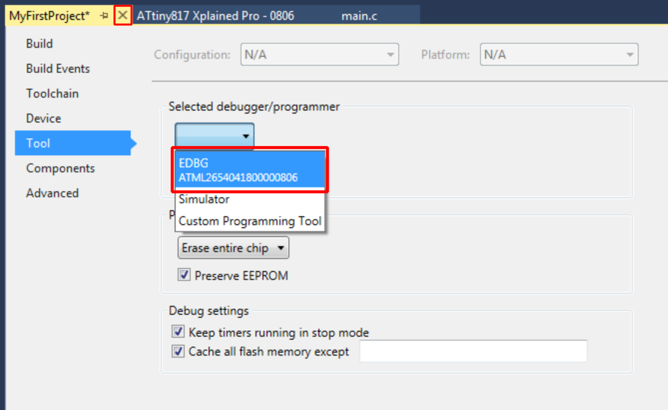
The Tool tab of the Project
Properties will open. In the drop-down menu, select the EDBG tool, as
indicated in the figure below. The interface should automatically initiate to UPDI
(Unified Programming Debugging Interface).Figure 2-12. Select Debugger/Programmer
in Project Properties
Tip: The serial
number of the tool will accompany its name in the drop-down menu. This serial
number is printed on the backside of each tool, allowing differentiation when
more than one is connected.
Tip: If using a different tool for the
following debug/program session, repeat these steps.
Warning: On the ATtiny817 Xplained Pro,
the EDBG is connected permanently to the target MCU. For a custom hardware solution, it
is necessary to ensure that the target device is powered and connected before launching
a debug session.
Result: The tool to
be used by Microchip Studio when launching a debug/programming session is now
specified.
Settings Verification
This section is a guide verifying the tool and project configuration setup by compiling
the empty project and writing it to the ATtiny817.
Todo: Verify the tool and project configuration setup done in the previous
sections.
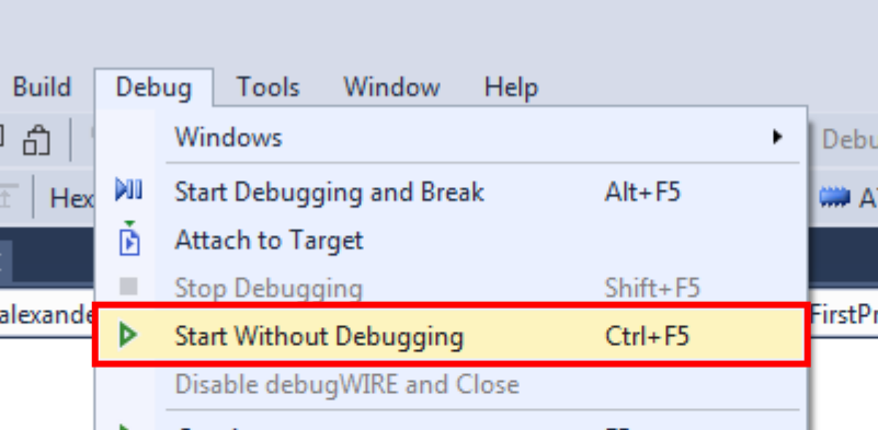
Clicking the Start Without Debugging
button in the Debug menu, as shown in the figure below, will compile and
write the project to the specified target MCU using the configured tool.Figure 2-13. Start Without
Debugging
When Microchip Studio builds the
project (automatically done when pressing Start Without Debugging),
several generated output files will show in the Solution Explorer window.
The following output files are generated:
EEP file: EEPROM content
written to the device.
ELF file: Contains
everything written to the device, including program, EEPROM, and
fuses.
hex file: Flash content
written to the device.
LSS file: Disassembled
ELF file.
MAP file: Linker info,
what did the linker do, decisions about where to put things.
SREC file: Same as hex
but in Motorola format.
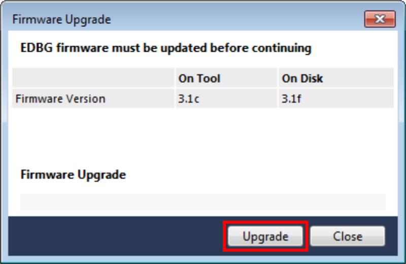
Info: If there is
new firmware available for the selected tool, the Firmware Upgrade dialog
will appear, as depicted in Figure 2-14. Click
the Upgrade button to start the firmware upgrade.Figure 2-14. Firmware Upgrade
DialogDepending on the state of the connected tool and the actual firmware upgrade,
the update may fail on the first attempt. This failure is ordinary. Disconnecting
and reconnecting the kit before clicking Upgrade again may resolve the
problem. After the completed update, the dialog should say 'EDBG Firmware
Successfully Upgraded'. Close the dialog box and make a new attempt at
programming the kit by clicking the Start Without Debugging button
again.
Result: The
following has been verified by compiling the empty project and writing it to the
ATtiny817:
The project is configured for
the correct MCU
The correct tool has been
selected
The tool's firmware is
up-to-date
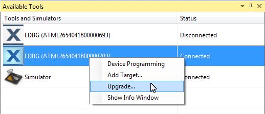
Under View > Available Tools,
you can see a list of available or recently used Tools. Here you can specifically
ask Microchip Studio to upgrade the firmware for a tool.Figure 2-15. Microchip Studio Available Tools (on view
menu)
The online versions of the documents are provided as a courtesy. Verify all content and data in the device’s PDF documentation found on the device product page.

 Tip: The serial number of the tool will accompany its name in the drop-down menu. This serial number is printed on the backside of each tool, allowing differentiation when more than one is connected.