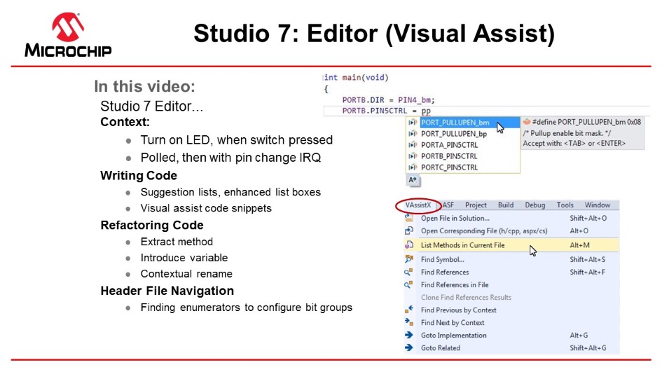
2.12 Editor: Writing and Re-Factoring Code (Visual
Assist)
The Microchip Studio Editor is powered by an extension called Visual Assist, a
productivity tool for refactoring, reading, writing, and navigating C and C++ code.
#include<avr/io.h>intmain(void)
{
PORTB.DIR = PIN4_bm;
while (1)
{
}
}
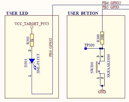
The ATtiny817 Xplained Pro design documentation schematic shows the connections for
the LED and button, as in the figure below. Figure 2-30. ATtiny827 Xplained Pro GPIO
Connection SchematicsFrom the schematics, the conclusions are:
The LED can be turned ON by
driving PB4 low
SW0 is connected directly to GND
and PB5 through a current limiting resistor
SW0 does not have an external
pull-up resistor
SW0 will be read as
'0' when pushed and '1' when released if
the ATtiny817 internal pull-up is enabled
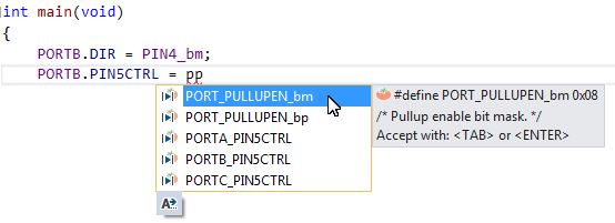
Enable the pull-up on PORTB5, using suggestion list and enhanced list box. Note
that suggestion lists support acronyms, so typing 'pp' PORT_PULLUPEN is the top
suggestion.
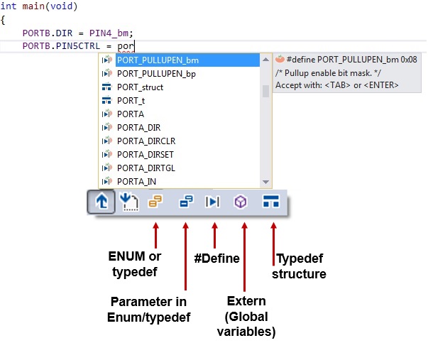
However, before hitting enter,
first type 'POR' then hit CTRL+SPACE, which will bring up the Enhanced Listbox
with all possible options.
Now it is possible to filter suggestions by type,
as indicated in the picture below.
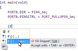
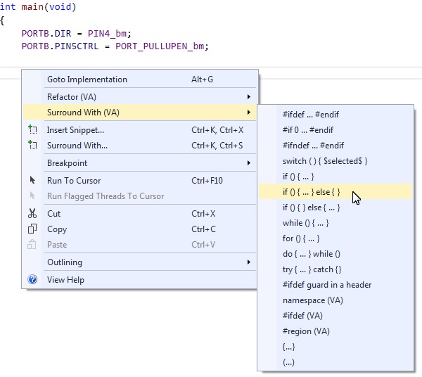
Test if SW0 is pressed, using
if( ){...}else{...} visual assist code snippet.
Typing 'if'
will bring up the option, or you could R-click and choose Surround
With (VA), which gives a complete list of snippets. This is editable
- you can add your snippets.
Test if the switch is pressed.
The if( ){...}else{...} condition turns the LED ON if pressed and OFF if
not. main.c should now look as
follows:
#include<avr/io.h>
intmain(void)
{
PORTB.DIRSET = PIN4_bm; /* Configure LED Pin as output */
PORTB.PIN5CTRL = PORT_PULLUPEN_bm; /* Enable pull-up for SW0 pin */while(1)
{
if (!(PORTB.IN & PIN5_bm)) /* Check switch state */
{
PORTB.OUTCLR = PIN4_bm; /* Turn LED off */
}
else
{
PORTB.OUTSET = PIN4_bm; /* Turn LED on */
}
}
}
Verify that LED0 lights up
when pushing SW0. Run the code by clicking Start Without
Debugging
(Ctrl+Alt+F5) to verify that LED0 lights up when clicking SW0 on the ATtiny817
Xplained Pro kit.
When the basic functionality is in place, let's refactor the
code to make it more readable.
Create functions LED_on( ) and
LED_off( ) using Refactor → Extract Method. When clicking SW0, the line
of code to turn the LED ON is executed. Highlight this line of code, right click
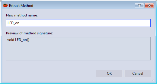
and go to it, as indicated in the figure below. Figure 2-31. Extract MethodAn Extract Method dialog will appear. Name the function 'LED_on' as
indicated in the following figure. Figure 2-32. Extract Method
DialogClick OK, and the code should change. A new function called
LED_on() should appear at the top of the file, with a
function call where the line of code used to be. Use the same method to
implement LED_off().
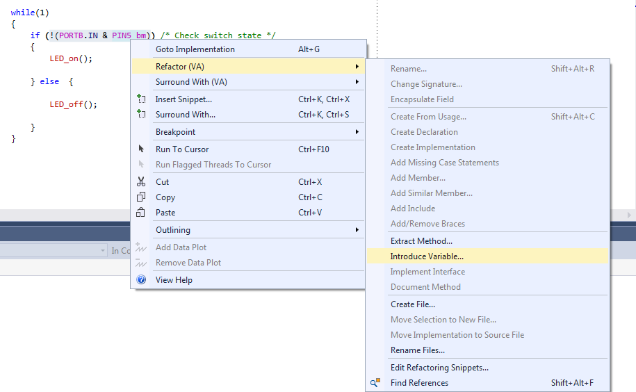
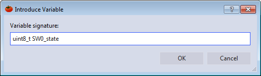
Create a variable for SW0
state, usingRefactor → Introduce Variable. Next, it is necessary to create a variable
for the SW0 state. Highlight the condition inside the if() in
the main() while(1) loop. Right click and go to it, as
indicated in the figure below.Figure 2-33. Introduce
VariableThe Introduce Variable dialog will appear, as depicted in Figure 2-34. Name the variable 'uint8_t
SW0_state'.Figure 2-34. Introduce Variable
Dialog
Tip: Change the
automatically generated bool return value to
uint8_t to avoid including an extra header to deal
with Boolean values.
Click OK, and the code should change. The
condition inside the if() statement references a variable
assigned to the variable on the line above, as shown in the code block below.
    while (1)
    {
    uint8_t SW0_state = !(PORTB.IN & PIN5_bm);
		if (SW0_state)
		{
			LED_on();
		}
		else
		{
			LED_off();
		}
    }
Create a function
SW_get_state,using Refactor → Extract Method. Select the right side of the
SW0_state assignment and extract a method for
SW_get_state.
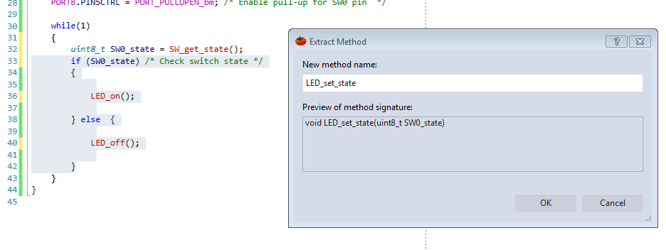
Implement a function
void LED_set_state(uint8_t state). Extract the
method. Microchip Studio will detect the argument SW0_state,
as indicated in Figure 2-35. Figure 2-35. Extract Method with
ArgumentClick OK, and the code should change. Now, there is another method
for setting the LED state.
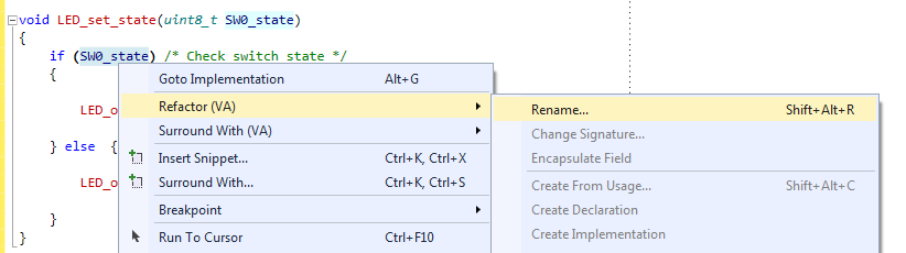
In function void
LED_set_state(uint8_t state) rename SW0_state to state using
Refactor → Rename. In a larger application, use this function for
setting the LED state in a context that is irrelevant to the SW0 state.
Microchip Studio is capable of contextual renaming. Use this feature to easily
rename the argument and avoid confusion. Inside the
LED_set_state() function, right click on the
SW0_state variable and go to Refactor → Rename, as
indicated in Figure 2-36.Figure 2-36. Contextual
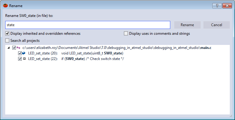
RenameThe Rename dialog will appear, as depicted in Figure 2-37. Rename the
SW0_state variable to 'state'. Microchip Studio will
detect all the variable occurrences with the same context as the one which has
been selected one, presented in a list, and able to be individually selected or
deselected.Figure 2-37. Contextual Renaming
DialogClick Rename, and the code should change. Observe that the argument
of LED_set_state() and all its references inside the function
have been renamed. The references to SW0_state in
main() have remained the same.
Create function definitions,
moving created functions below main().
main.c should now
look as follows:
#include<avr/io.h>voidLED_on(void);
voidLED_off(void);
voidLED_set_state(uint8_t state);
uint8_t SW_get_state(void);
intmain(void)
{
PORTB.DIRSET = PIN4_bm; /* Configure LED Pin as output */
PORTB.PIN5CTRL = PORT_PULLUPEN_bm; /* Enable pull-up for SW0 pin */while(1)
{
uint8_t SW0_state = SW_get_state(); /* Read switch state */
LED_set_state(SW0_state); /* Set LED state */
}
}
uint8_t SW_get_state(void)
{
return !(PORTB.IN & PIN5_bm); /* Read switch state */
}
voidLED_off(void)
{
PORTB.OUTSET = PIN4_bm; /* Turn LED off */
}
voidLED_on(void)
{
PORTB.OUTCLR = PIN4_bm; /* Turn LED on */
}
voidLED_set_state(uint8_t state)
{
if (state)
{
LED_on();
}
else
{
LED_off();
}
}
The online versions of the documents are provided as a courtesy. Verify all content and data in the device’s PDF documentation found on the device product page.

 (Ctrl+Alt+F5) to verify that LED0 lights up when clicking SW0 on the ATtiny817
Xplained Pro kit.
(Ctrl+Alt+F5) to verify that LED0 lights up when clicking SW0 on the ATtiny817
Xplained Pro kit.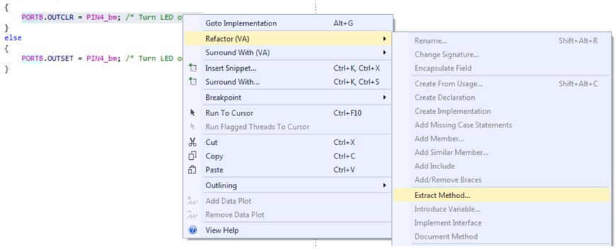
 Tip: Change the automatically generated bool return value to uint8_t to avoid including an extra header to deal with Boolean values.Click OK, and the code should change. The condition inside the if() statement references a variable assigned to the variable on the line above, as shown in the code block below.