2.16 Debugging 3: I/O View Memory View and Watch
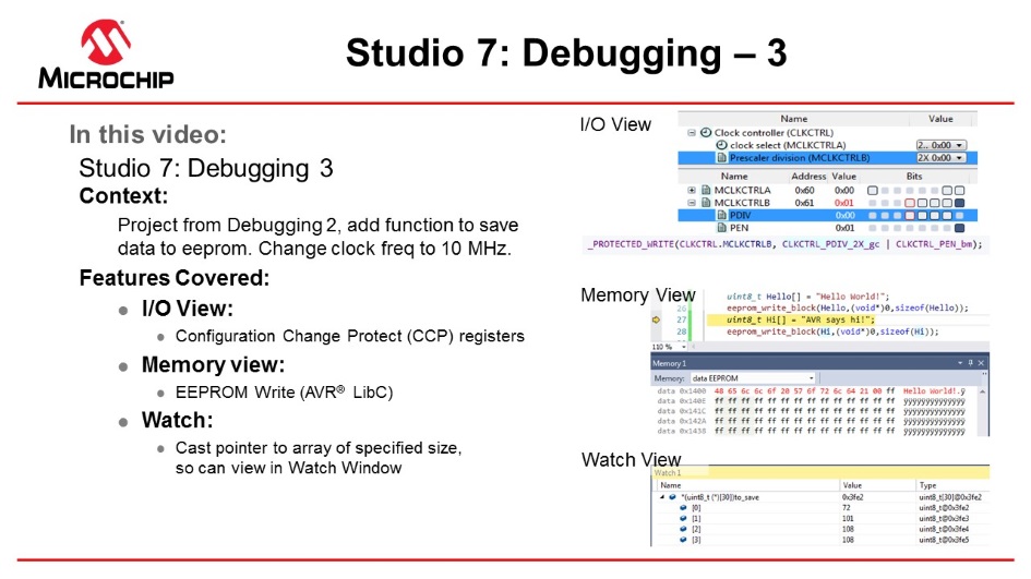
This section covers more advanced debugging topics with Microchip Studio as both video (linked below) and hands-on document. The main topics are using I/O View to work with Configuration Change Protected (CCP) registers, Memory View to validate EEPROM writes, and the Watch window to cast pointers as an array.
I/O View
The I/O view provides a graphical view of the I/O memory map of the device associated with the
active project. This debug tool will display the actual register content when
debugging, allowing verification of peripheral configurations. It can also be used
to modify the content of a register without having to recompile.
Todo: Use I/O view
to:
- Get an overview of the device memory map
- Check current peripheral configurations
- Modify peripheral configurations
- Validate configuration changes
- Remove all breakpoints and start a new debug session.
- Break code execution by
pressing the Break All button
 .
. - Open the I/O view from the top menu bar by going to Debug → Windows → I/O.
- Scroll through the list of
peripherals and select I/O Ports (PORTB). Find the OUT
register and click on Bit 4 in the Bits column, so the
corresponding square changes color, as depicted in Figure 2-57. Observe that clicking Bit 4 in
the PORTB.OUT register toggles the output level on GPIO pin PB4, which
controls the LED on the ATtiny817 Xplained Pro.
Figure 2-57. Manipulate Bit Value in Register Using I/O View 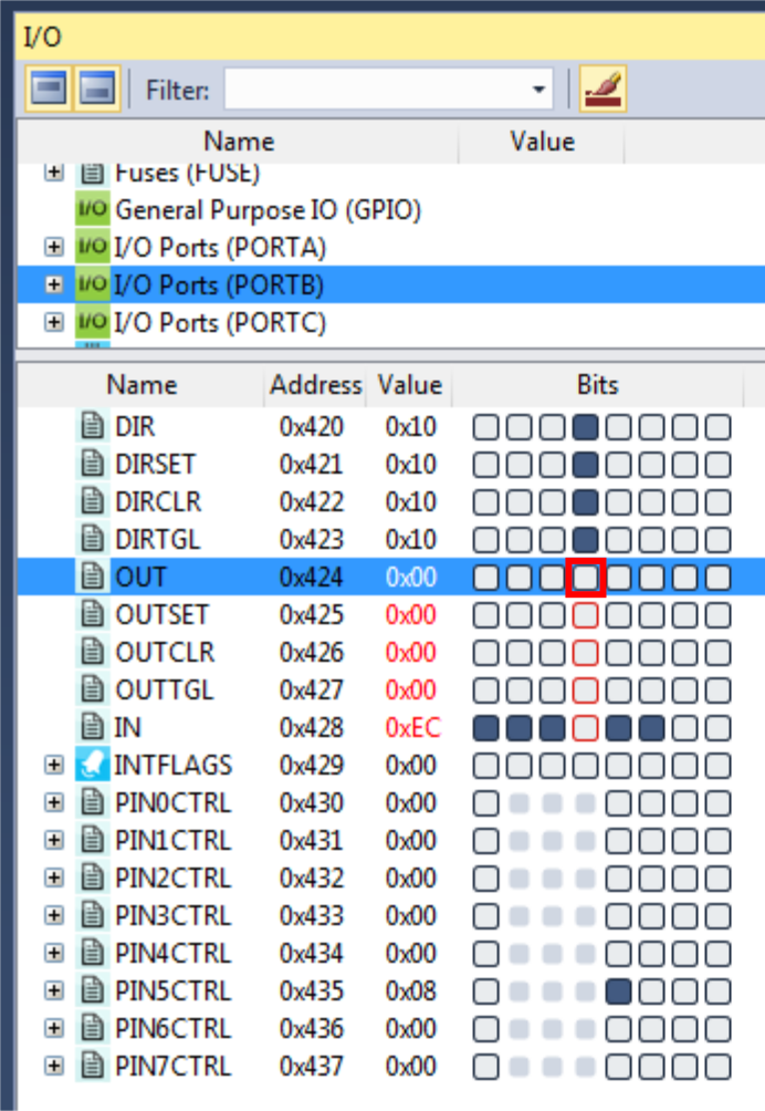 Info: The I/O view is refreshed after modifying any register, and all detected changes are highlighted in red.Tip: Modify multiple bits simultaneously by double clicking the value field and typing in the desired value to be assigned to the register.
 - Expand the Clock controller
(CLKCTRL) in the I/O view, and answer the following questions:
- What is the currently selected clock source (Clock select)?
- What is the configured prescaler value (Prescaler division)?
- Is the main clock prescaler enabled (MCLKCTRLB.PEN)?
Result: Configure the Clock controller with the ATtiny817 default clock settings; the main clock runs from the internal RC oscillator with prescaler enabled and a division factor of six.Info: The default clock configuration ensures that the device will execute code reliably over the entire supported operating voltage range, 1.8V to 5.5V. The Xplained Pro kit powers the ATtiny817 at 3.3V. According to the 'General Operating Ratings' section in the device data sheet, device runs safely at 10 MHz with a 3.3V supply. - The code will now be changed
to run the ATtiny817 at 10 MHz. Modify the start of
main() as
below:
int main(void) { /* * Set the Main clock division factor to 2X, * and keep the Main clock prescaler enabled. */ CLKCTRL.MCLKCTRLB = CLKCTRL_PDIV_2X_gc | CLKCTRL_PEN_bm; - Start a new debug session to recompile the project and program the device.
- Halt code execution by
clicking
 . Examine the clock settings in I/O view,
depicted in Figure 2-58.
. Examine the clock settings in I/O view,
depicted in Figure 2-58.Figure 2-58. Clock Settings in I/O View Remain Unchanged  Result: There is a problem! The prescaler remains unchanged.
 - Select the MCLKCTRLB
register in the I/O view, as indicated in Figure 2-59.
Figure 2-59. Select MCLKCTRLB in I/O View 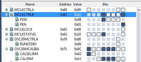
- Push F1 on the keyboard to
bring up a web-based register description.Info: Internet access is required to use the web-based register description. Refer to an offline version of the ATtiny817 data sheet if internet access is not available.
- Find out if any access
restrictions apply to the MCLKCTRLB register.Result: The Configuration Change Protection (CCP) mechanism protects the register. Critical registers are configuration change protected to prevent unintended changes. As described in the data sheet, these registers can be modified only when following the correct unlock sequence.
- Replace the line of code,
which was just added, with the
following:
_PROTECTED_WRITE(CLKCTRL.MCLKCTRLB, CLKCTRL_PDIV_2X_gc | CLKCTRL_PEN_bm);Info: _PROTECTED_WRITE() is an assembly macro that ensures meeting timing requirements for unlocking protected registers. It is recommended to use this macro when modifying protected registers.Tip: Right click the macro name in the code and select Goto Implementation to navigate to the macro implementation. This is also possible by placing the cursor at the macro name in the code and pressing Alt+G on the keyboard. Use the same process for variable declarations and function implementations. - Stop the previous debug session and launch a new session to program the device with the changes.
- Break code execution and use
the I/O view to verify that the prescaler is now successfully set to 2X, as
indicated in Figure 2-60.
Figure 2-60. Clock Settings in I/O View Changed Successfully 
Tip: The Processor
Status window is the register view tool for the AVR Core. Open this tool from
the top menu bar by going to Debug → Windows → Processor Status. This
window will provide a detailed view of the status of the internal AVR Core
registers. Use this view to check if global interrupts are enabled; look for the
I-bit in the status register.
Result: The
capabilities of the I/O view have been used to find and fix a bug in the
project.
Memory View
ToDo: Write two
strings to the beginning of the ATtiny817 EEPROM and use the Memory view to
verify the EEPROM contents.
- Add #include <avr/eeprom.h> after the #include <avr/io.h> line.
- Add the following code before the while(1) loop in main():
uint8_t hello[] = "Hello World"; eeprom_write_block(hello, (void *)0, sizeof(hello)); uint8_t hi[] = "AVR says hi"; eeprom_write_block(hi, (void *)0, sizeof(hi)); - Place a breakpoint next to the first call to
eeprom_write_block() as in Figure 2-61.
Figure 2-61. Breakpoint to Halt for Checking EEPROM 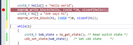
- Start a new debug session to program the device with the updated code.
- After the breakpoint is hit, open the memory window from the top menu bar by going to Debug → Windows → Memory → Memory 1. Look at the current content of the EEPROM.
- Push F10 on the keyboard to step over the eeprom_write_block() call and verify the EEPROM write.
- Allow the ATtiny817 to execute the next
EEPROM write before verifying the write using the Memory view. The view
should appear as in Figure 2-62 at each
interval, respectively.
Figure 2-62. Memory View Updating After EEPROM Writes 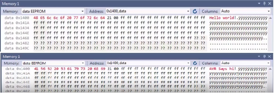 Tip: The Memory view tool can also be used to investigate the contents of other AVR memory sections, including the program memory. This can be useful when debugging bootloaders.
Result: The content of
the EEPROM is updated after each call to
eeprom_write_block(). The updated content is highlighted in
red, and the ASCII interpretation of the EEPROM content matches the written
strings. Therefore, the contents of EEPROM after writing to it have been
verified using the Memory view.
Watch Window
Watch Window is covered in more detail in section Debugging 2: Conditional- and Action-Breakpoints . However, the note on how to cast pointers as an array in the Watch window is repeated here.
Info: A variable can
also be added to the Watch window by clicking on an empty field name and typing
the variable name. This way, it is even possible to cast a variable to a
different data type for better readability in the Watch window, which is
especially useful if it is required to look at an array passed to a function as
a pointer.
For example, if an array is passed to a function, it will be passed
to the function as a pointer, which makes it impossible for Microchip Studio
to know the length of the array. If the array length is known and needs
investigation in the Watch window, the pointer can be cast to an array using
the following
cast:
*(uint8_t (*)[<n>])<name_of_array_pointer>Test this on the SW0_edge_count variable
by entering the following in an empty name field in the Watch
window:
*(uint8_t (*)[5])&SW0_edge_countResult: Microchip
Studio has now been used to inspect and modify the contents of variables in the
code.
Code Used for Debugging 3
#include <avr/io.h>
#include <avr/eeprom.h>

void LED_on(void);
void LED_off(void);
void LED_set_state(uint8_t state);
uint8_t SW_get_state(void);
uint8_t SW_get_state_logic(void);

int main(void)
{
    PORTB.DIRSET   = PIN4_bm;          /* Configure LED Pin as output */
    PORTB.PIN5CTRL = PORT_PULLUPEN_bm; /* Enable pull-up for SW0 pin  */

	_PROTECTED_WRITE(CLKCTRL.MCLKCTRLB, CLKCTRL_PDIV_2X_gc | CLKCTRL_PEN_bm);

	uint8_t Hello[] = "Hello World!";
	save(Hello,sizeof(Hello));
	uint8_t Hi[] = "AVR says hi!";
	save(Hi,sizeof(Hi));

	while(1)
    {
        uint8_t SW0_state = SW_get_state_logic(); /* Read switch state */
        LED_set_state(SW0_state);           /* Set LED state     */
    }
}

void save(const uint8_t* to_save, uint8_t size)
{
	eeprom_write_block(to_save,(void*)0,size);
}

uint8_t SW_get_state()
{
	return !(PORTB.IN & PIN5_bm);
}

uint8_t SW_get_state_logic(void)
{
    static uint8_t SW0_prv_state  = 0;
    static uint8_t SW0_edge_count = 0;

    uint8_t SW0_cur_state = !(PORTB.IN & PIN5_bm); /* Read the current SW0 state  */
    if (SW0_cur_state != SW0_prv_state)            /* Check for edges             */
    {
        SW0_edge_count++;
    }
    SW0_prv_state = SW0_cur_state;                /* Keep track of previous state */

    /*
     * Report the switch as pushed when it is pushed or the edge counter is a
     * multiple of 3
     */
    return SW0_cur_state || !(SW0_edge_count % 3);
}

void LED_off(void)
{
    PORTB.OUTSET = PIN4_bm; /* Turn LED off  */
}

void LED_on(void)
{
    PORTB.OUTCLR = PIN4_bm; /* Turn LED on */
}

void LED_set_state(uint8_t state)
{
    if (state)
    {
        LED_on();
    }
    else
    {
        LED_off();
    }
}
